It’s been a long time since the last update and I really do mean to keep this blog going. However, I know nobody wants to read my babbling blog on a regular basis. This is more of a project documentation…
So what have I been up to since February? Well teaching 16 students a week (in 2.5 days) and playing weekly with the Augusta and Greenville Symphonies. Anderson University gave their Second Annual Night of Percussion performance followed by a two high school tour the next day. The students played very well. It’s been a great spring, musically speaking. Maybe I’ll make a separate post about all of that after the end of May. (Auditions take precedent.)
With the lathe, I’ve been working to get a power feed on my leadscrew and I’m almost done. I originally tried a wiper motor and “Pulse Width Modulator (PWM)”, but it proved to be too weak. I’ve already bought a better controller and picked up a Bodine geared motor, just need to wait for it to all arrive.
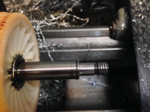
Wiper motor shaft turned down to accept shaft extension
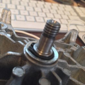
Wiper motor put together with new snap ring
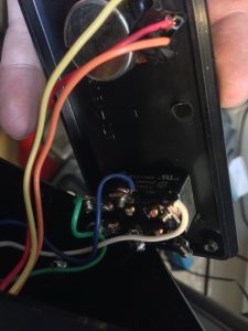
Inside the control box (version…1?)
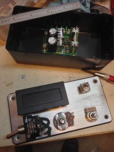
Getting ready to assemble the PWM
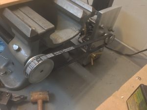
Power feed setup (with wiper motor)
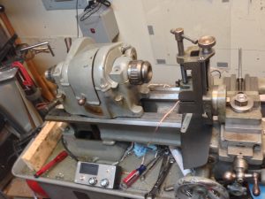
To remove the leadscrew, I had to remove the gearbox and headstock
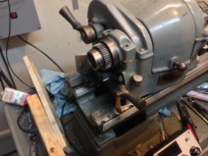
Headstock moved to get to the gearbox screws
The milling attachment has proved to be a very useful tool with the lathe. Someday (as most people will milling attachments will say) I’d like to get a nice mill, but I’ll need a new shop space before that happens. If I could replace my drill press entirely with a mill, I’d go for it. (And I think I can, but I need more space first.)

Here you can see the milling attachment on the lathe, but leadscrew was removed for adding the pulley for the power feed
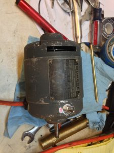
I’ve made a few shaft flats, square keys (chuck key for lathe), and milled screw driver slots for some projects. One such project is my rebuilding of a Dumore 44 Tool Post Grinder. That will deserve a full write up when I’m done. (Hey future Daniel, come put a link right here for that when you’re done.) In the meantime, I’ve replaced the motor bearings, cleaned up the armature, made new brush holders and caps, and added a power switch, which I’ll likely replace with a DPDT on-off-on switch to change directions of rotation. I plan to dig into the spindle portion of the rebuild soon, as well as derust the metal parts included in the kit.
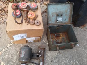
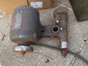
Dumore 44 TPG, as it arrived (rusty!)
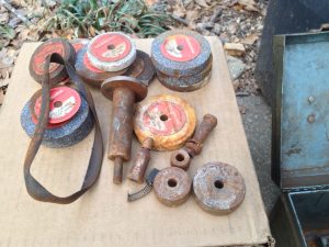
Everything needed was included!
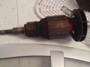
I was able to afford the TPG because it “didn’t work.” This armature was very dirty.
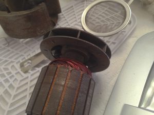
I put the armature and a bunch of parts in a recently purchased UltraSonic Cleaner
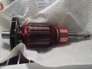
After cleaning and cleaning up with emory cloth on the lathe
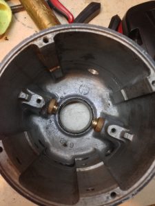
Dumore 44 motor housing after ultrasonic cleaning, brush holder installation, and 1/2″ hole drilling for new switch
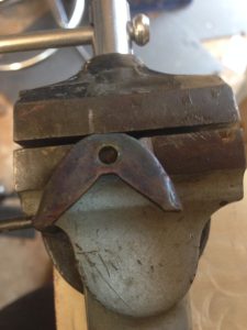
Way felt holders as removed from lathe
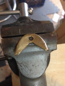
Way felt holder after ultrasonic cleaning
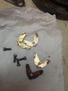
A quick nylon Dremel brushing and these things are shiny!
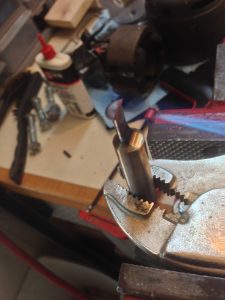
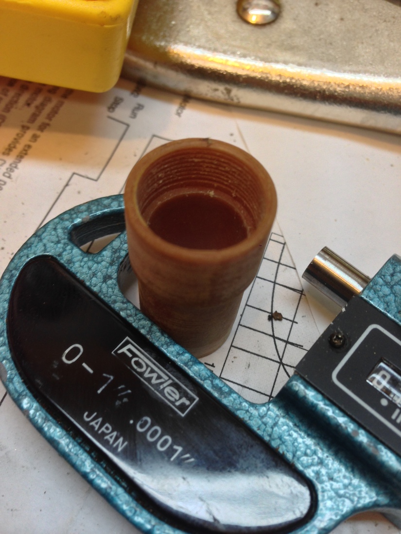
Part of the motor rebuild on the Dumore involved internal threading of a 5/8-32 thread. I made a internal threading tool from heat treated 01 steel.
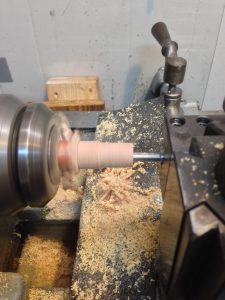
The phenolic I bought cut more like wood than plastic
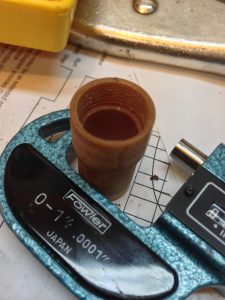
Finished phenolic brush holder (without brass insert which was recycled)
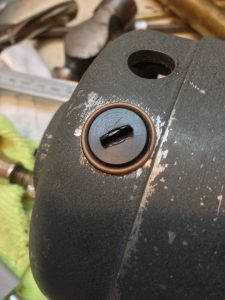
Brush holder with delrin cap (5/8-32 thread, milled 3/8″ screwdriver slot)
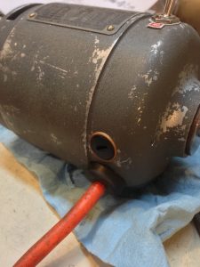
Rebuilt Dumore 44 with “new” power cord, new switch, and new brush holders (and bearings)
My Digital Read Out (DRO) is also (finally!) done. I’m happy with how it turned out. I’m still going to calibrate it further which involves some math and very precisely machined measuring tools. That shouldn’t take too long. Again, someday, I’ll write up a detailed blog of all that went into that project, simply because I had no business getting into such an involved build. But I learned a lot of stuff along the way and I’m sure there are many people who can benefit from my failures there.
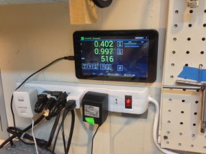
Using the DRO (table attached to wall with velcro for easy removal)
One thing I really am glad I did and want to share about the DRO – instead of powering it with a standard USB wall charger, I ran a wall charger to a 4pdt switch, then from there to a USB battery pack (using half the 4pdt switch). The other half of the switch directs the power from the USB battery pack to the DRO, so instead of dealing with electrical noise and the VFD, it’s isolated from any possible ground loops on its own power source. I got sick of plugging in and unplugging the battery back, so I spliced the wires to the switch and hid it in the control box. Up position uses battery pack power, middle is off, and down position charges the pack.
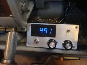
DRO controller (tach on top, top right is battery pack power)
The tachometer on the control box is nice because it doesn’t require the DRO to be operating and it also helps to “average out” the DRO readings, which aren’t the same. So in affect I have two tachometers, both using Hall sensors. The DRO tachometer has ten magnets and the box tach has one, but they’re pretty close in readings no matter how I change the magnets.
On the control box, the original DC motor control knob and power switch are still in place, but the switch was instead used for the DRO power. I’ll eventually hook the knob back up and add a new switch or two, but real estate on that box is becoming precious! I may have to redesign the front of the box… too bad RadioShack is going out of business as these boxes will be harder to come by in the future!
Still to do on the lathe:
– finish up the power feed
– install a new belt for the flat pulleys
– rebuild the Tool Post Grinder (TPG)
– use the rebuilt TPG to grind the face and jaws on the chuck
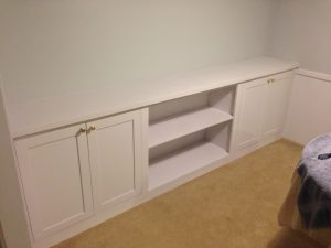
In other news, I finally finished the built-in cabinets I started last May. I sprayed a coat of primer and a coat of enamel and they look great! (The wife is happy, and that’s what matters most.) We’ve since replaced the brass knobs with better looking knobs to match the rest of the cabinets in the living room. The doors have soft close hinges on them. I made the doors with MDF and poplar, face frame with poplar, the top was MDF and veneer, and the rest birch plywood.

Leave a Reply