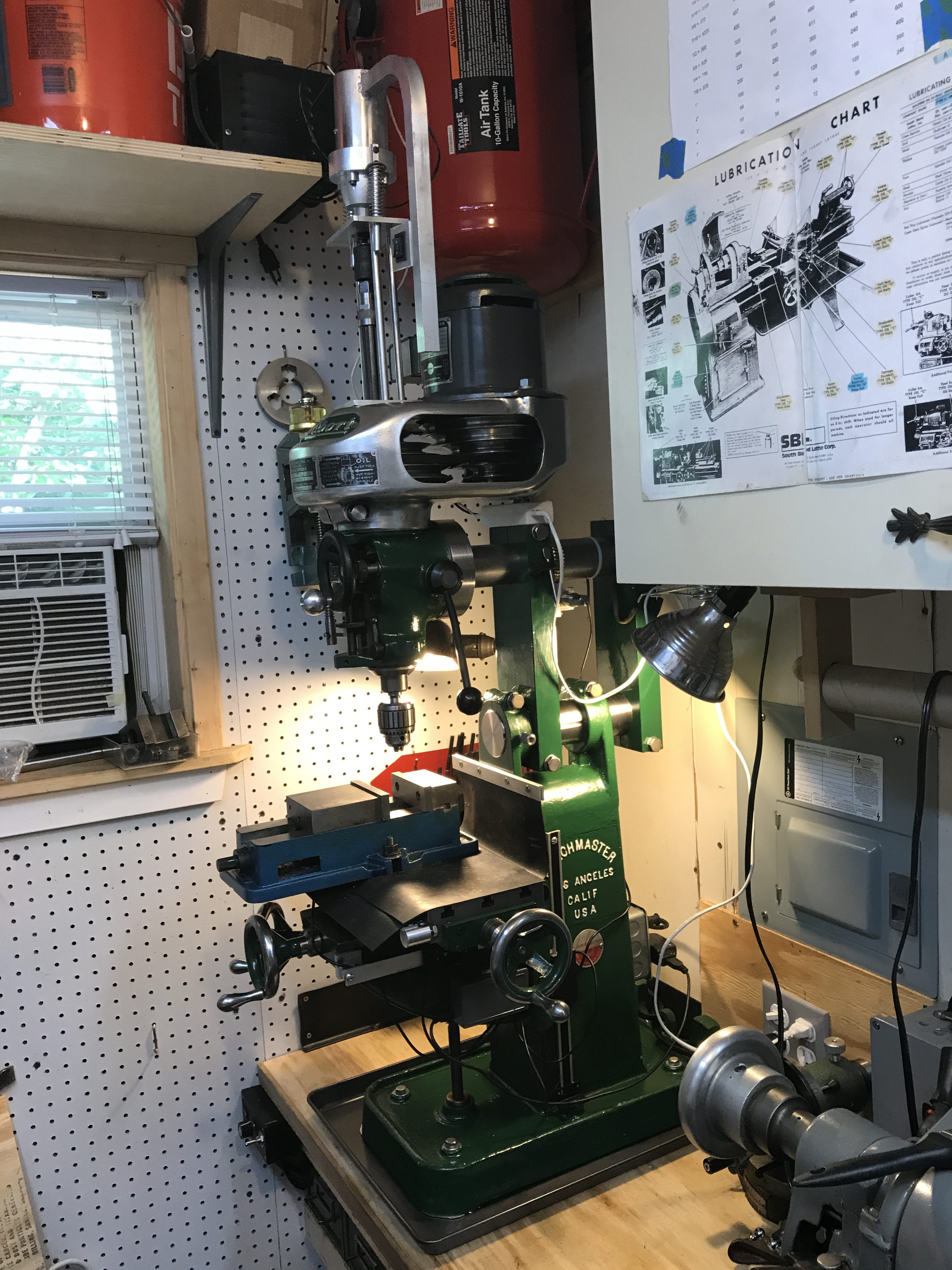
As the title says, here is the Finale! However, I’m sure I’ll be tweaking this thing until the day I’m done using it. Everything went together really nicely, I only had to modify my idea in one minor way, and I’m very happy with how the mill operates. I do believe I lost a bit of rigidity from the original design of the Benchmaster, but not enough to sway me from enjoying this modification.
I believe the M head is a perfect fit for this mill project! I’ve already used the mill to work on the power drawbar idea I’m now using. It’s not perfect and I have plans to tweak it a bit more, but …it works and it’s far better than holding a 1-1/4″ and 3/4″ wrench above my head. (Speaking of, I built my bench too high, but I’m going to live with it for a few weeks and then decide if I want to build a step-up platform. I’m building a shed in a little bit, so I’ll have spare lumber in the end.)
First things first, since the last post, I altered my design so that the riser columns didn’t span the outside of the original BM casting, but rather interlaced with it. After putting the whole thing together, I realized I failed to take into account increased table travel up the knee ways; the riser column ran into the table. This new setup might give up some rigidity, but I didn’t shorten the span between the risers, I just moved them back about 4″. To do so, I had to mill the keyways longer on the upper and lower rams. That took about 20 minutes at a friend’s shop.
While putting the head back together the second time, I opted to use a shorter belt. The original M Head belt size was 3L290 (3/8″ width, 29″ long), but I went one inch shorter, 3L280 and it was perfect. Maybe I placed the bolts in a different place than the original when I fixed the broken aluminum casting…
Either way, once done, I trammed the head using the worm gear. Even with backlash, it was very, very easy to dial the head in. I used a 6″ bearing race to give a nice even surface for the dial gauge to sweep across. Side to side was zeroed and back to front was about +/- .0005. I decided not to address that – tightening down various column bolts helped bring it in a little closer, but it’s not worth shimming. I may check it in another year or so and see if it falls in a little more evenly. (It was lower in the back, meaning it could settle into perfect.)

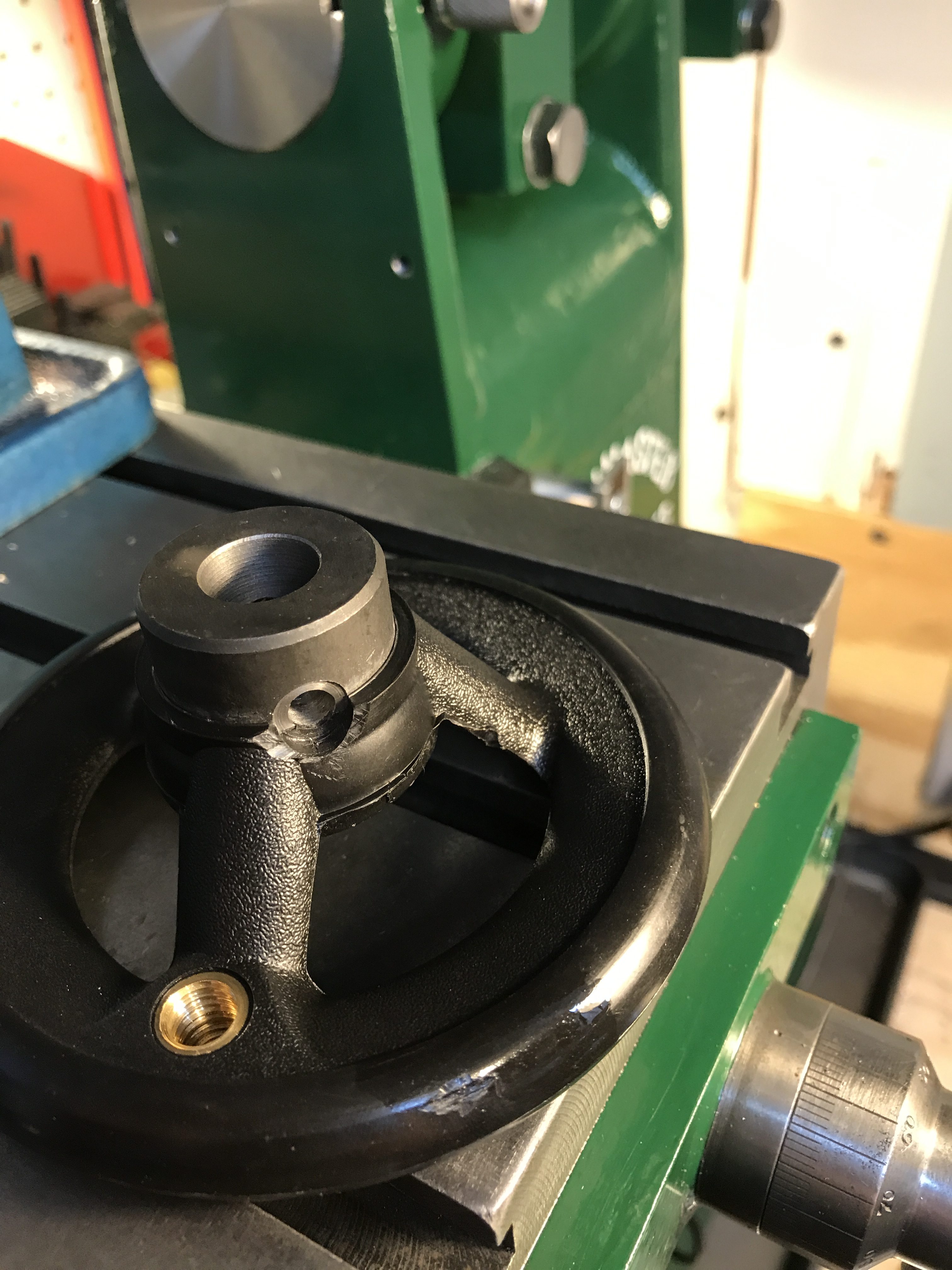
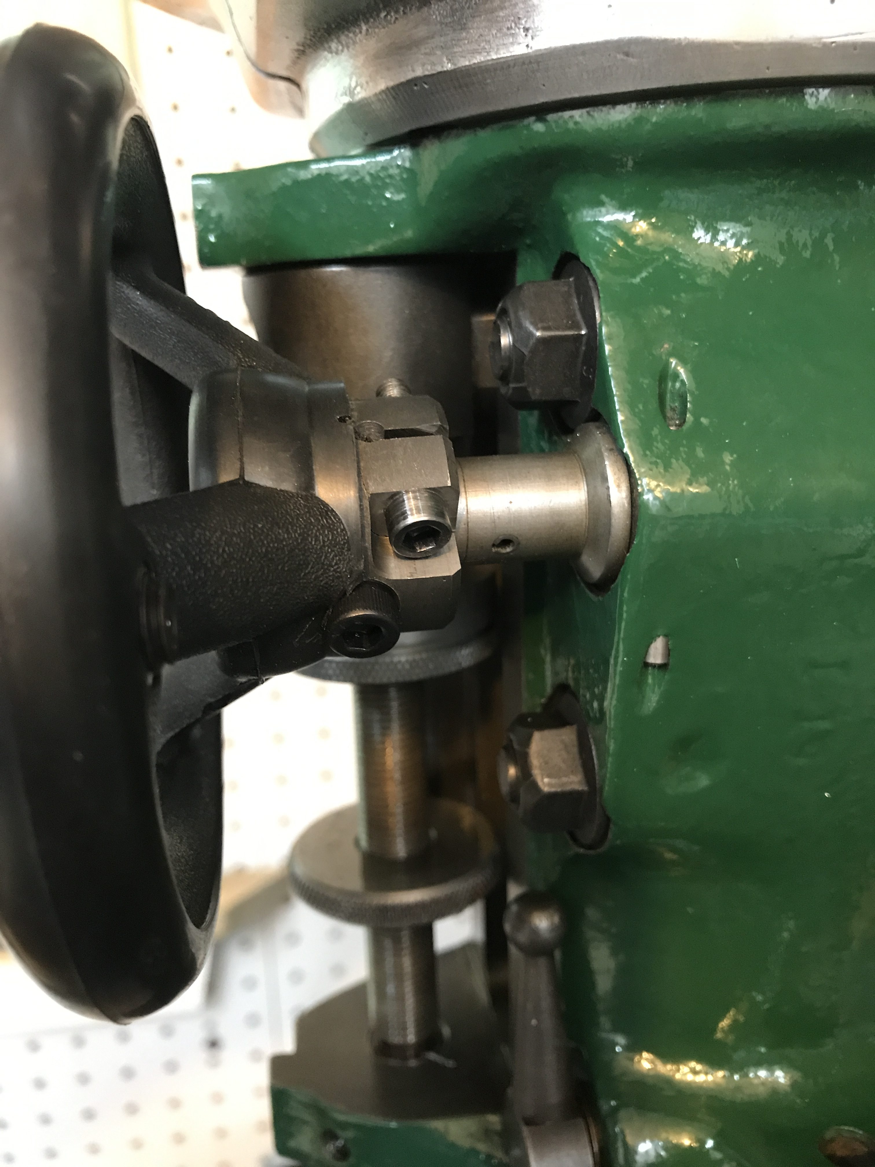
Next task to address was the fine feed wheel. I’ve read all over the internet that people seem to hate these things. I think it’s because they are too big and rattle. So I mounted a 4″ wheel and cinched it down onto the shaft using a cap screw. The bore was 1/2″, I drilled a hole about 1/8″ diameter 3/8″ in from the end and used a Dremel wheel to cut the slit into that hole. The second bolt was used as the cross pin to engage the pinion shaft on the head. I had an aluminum ball laying around so I drilled it out for a cap screw and use it as a revolving knob. I press fit a brass plug into the front for cosmetics and couldn’t be happier.


Using the mill to do certain parts of the fine feed wheel was a nice satisfying feeling, however, making the power drawbar was even better. I used just about ever feature on the mill to get the job done.
The drawbar is based off the motor and nose cap to the Harbor Freight #62874. I removed the switch and plastic housing and made an aluminum housing for the motor and “hammer.”
I power it with an old laptop battery charger and have a momentary forward-reverse (DPDT) switch mounted on some aluminum angle and a handle I made by bending a piece of 3/4″ aluminum tubing on my ring roller. (I’ll make a blog post about that another time…) The handle is welded to the aluminum housing. I had to make an 8″ riser platform to hold the springs and and guide shafts up.
The socket is a 1/2″ drive 12 point 3/4″ impact socket. I found a 1/4″ hex drive to 1/2″ square drive adapter at the big box store and Loctited it into the impact driver.


It’s ridiculously high and looks even crazier on the mill, but it’s worth it since it makes tool changes easy. It takes about 10 seconds to change out a collet. I plan to make two guide pieces that will connect to the bottom of the shafts with the springs on them, and ride on (perhaps in bronze or plastic sleeves) the lower riser shafts. It’ll keep the tool from leaning over from the weight of the handle. Speaking of weight, everything was made with aluminum to try and keep it as light as possible.
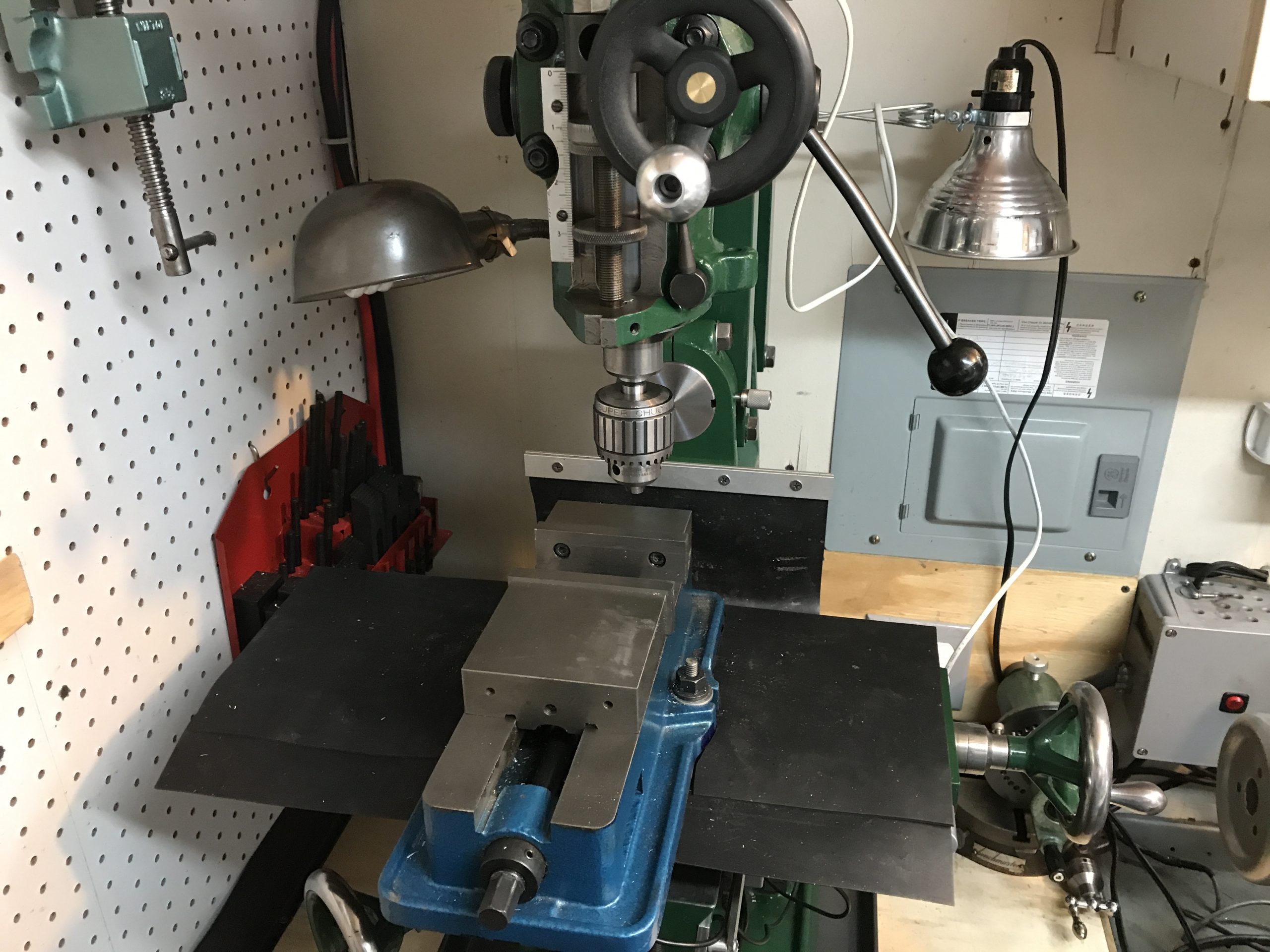
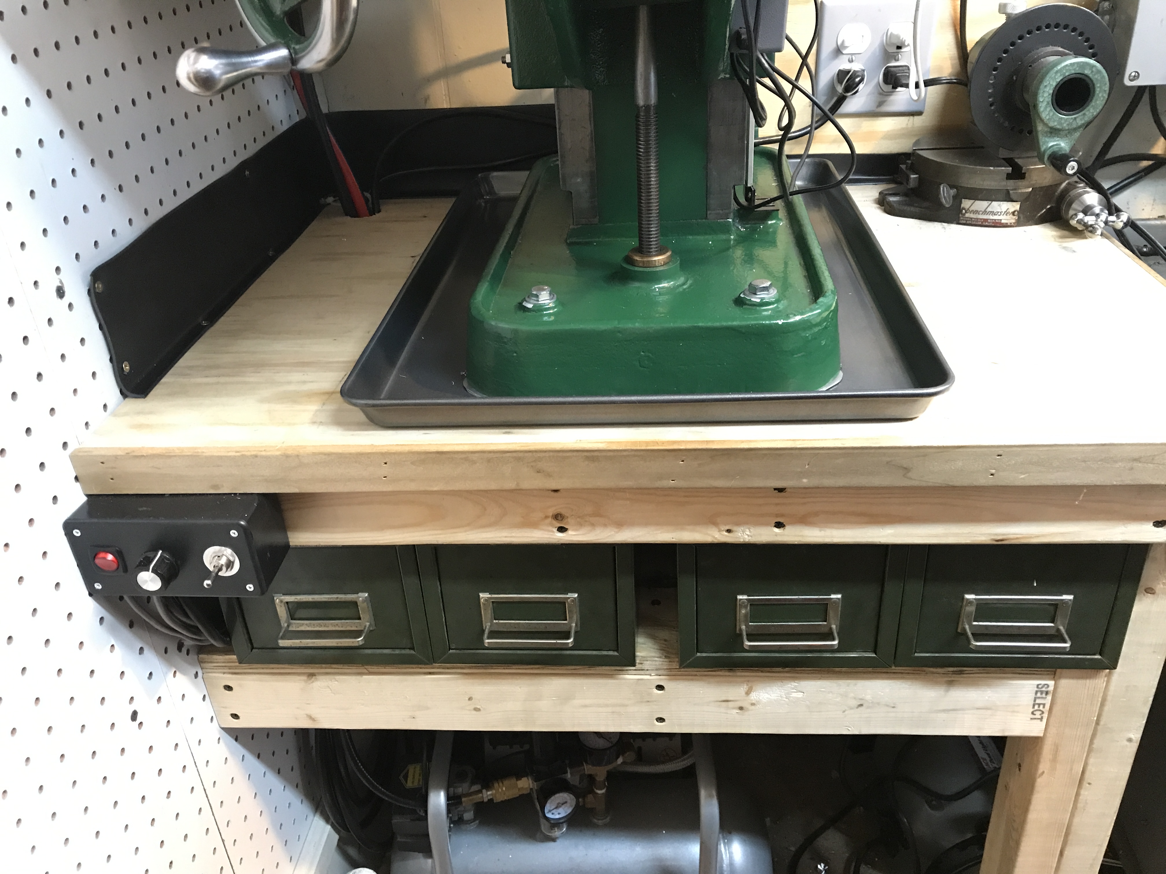
All the rubber mats have been reinstalled and some lighting put in place.

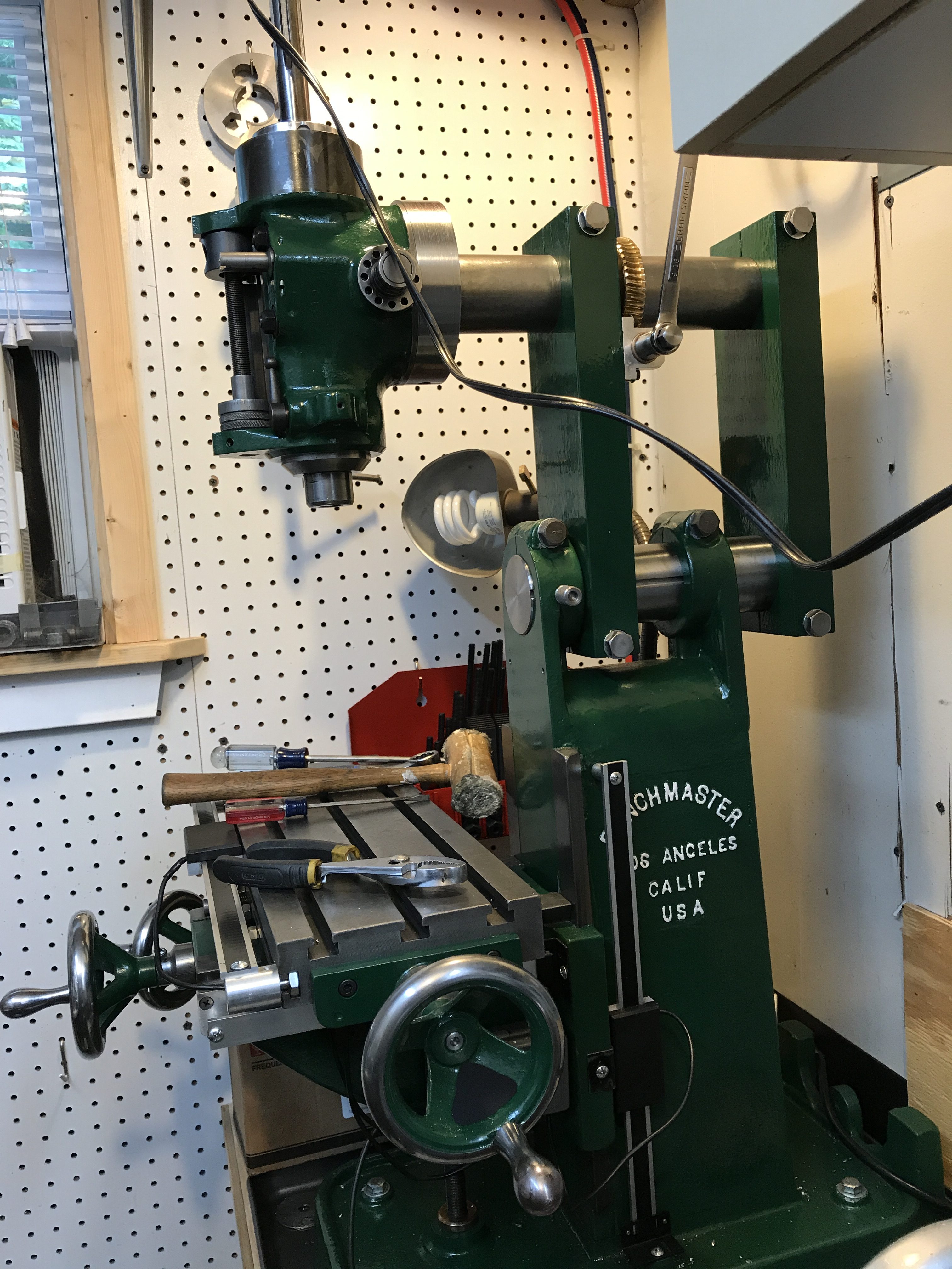
I decided to save the badge I made for the BM head guard I had cast and put it on the column. I think it looks nice there. I also wired an outlet so that only one plug is needed to power the VFD, light, and DRO (TouchDRO and iGaging scales – perhaps a post about that another time…) The power drawbar may be hardwired so it only powers up when the VFD is on… haven’t decided that far yet.

The VFD is mounted under the bench and the controller is placed just under the lip of the table. I had originally planned on housing the controls in the motor’s box, but it’s just too high and far away. This is safer and easier to manipulate. The Steelmaster drawers are perfect for holding tooling and various cutters. The cookie sheet helps to keep spindle oil and chips from getting all over the table. (Note the clearance for the knee screw between the Steelmaster drawers.)
(Adding to the original post here….)
One thing I forgot to mention is how I removed the rattle from the splines and front pulley. Teflon tape… the tape timpanists (not plumbers) use on the bearing edge of the copper bowl. I had a few rolls sitting around and grabbed the thinnest I had. I originally tried to run tape down 3 altering splines but it was too tight. I then tried 180 across from each other on two splines and it works very, very smoothly. There is a tiny bit of friction moving the quill down, but it’s better than a loud machine. With the motor running quiet and the splines silent, I could easily accidentally leave this machine running and not know it! (As for plumber’s teflon tape – it’s not the same thing and not nearly as robust as the bearing edge tape.)
So, Internet, there you have it. Everybody said it wouldn’t work out, it would be top heavy, it would look crazy, it’s impossible, etc etc… Thank you for the challenge, I enjoyed it and now I’m enjoying the fruits of my labor! This thing is perfect for my needs. If I need something bigger, I just head to my friend’s shop and use the full size machines there. But, for my tiny little 6’x12′ workshop, this machine is perfect. And this machine is now officially named “Tator.” I can say I’m going to “tinker with Tator.”
World, meet Tator, the Benchport, Bridgemaster, Benchmaster Bridgeport, Benchtop Bridgeport, whatever. It’s Tator.
Leave a Reply