
Well, we’re almost there! Of all the projects I have going on this summer, I’ve basically been going at this one the last week or two at full throttle. A few more hours in the shop and I’m positive the mill will be assembled and done. At the time of this writing, the riser columns are done, painted, and installed, along with the lower and upper rams. I need to adjust gibs on all three ways. I’m retapping the holes for the gib screws as I go and may alter a few of the screws’ points. In the future, I may make better axis locking bolts. I have ideas…
Quill Feed Handle
The handle that came with the mill head (parts) was a shop made aluminum thing that just didn’t work. The handle would run into the head. (Imagine hitting your own head with your hand…) So I made a new hub for it and reused the old handle. The hub is 12L14 stock with a 1″ bore, and a 3/16″ stainless steel pin. After finishing and cleaning up the metal, I applied some gun bluing to darken the metal a bit. I think it turned out really nice.
Finished parts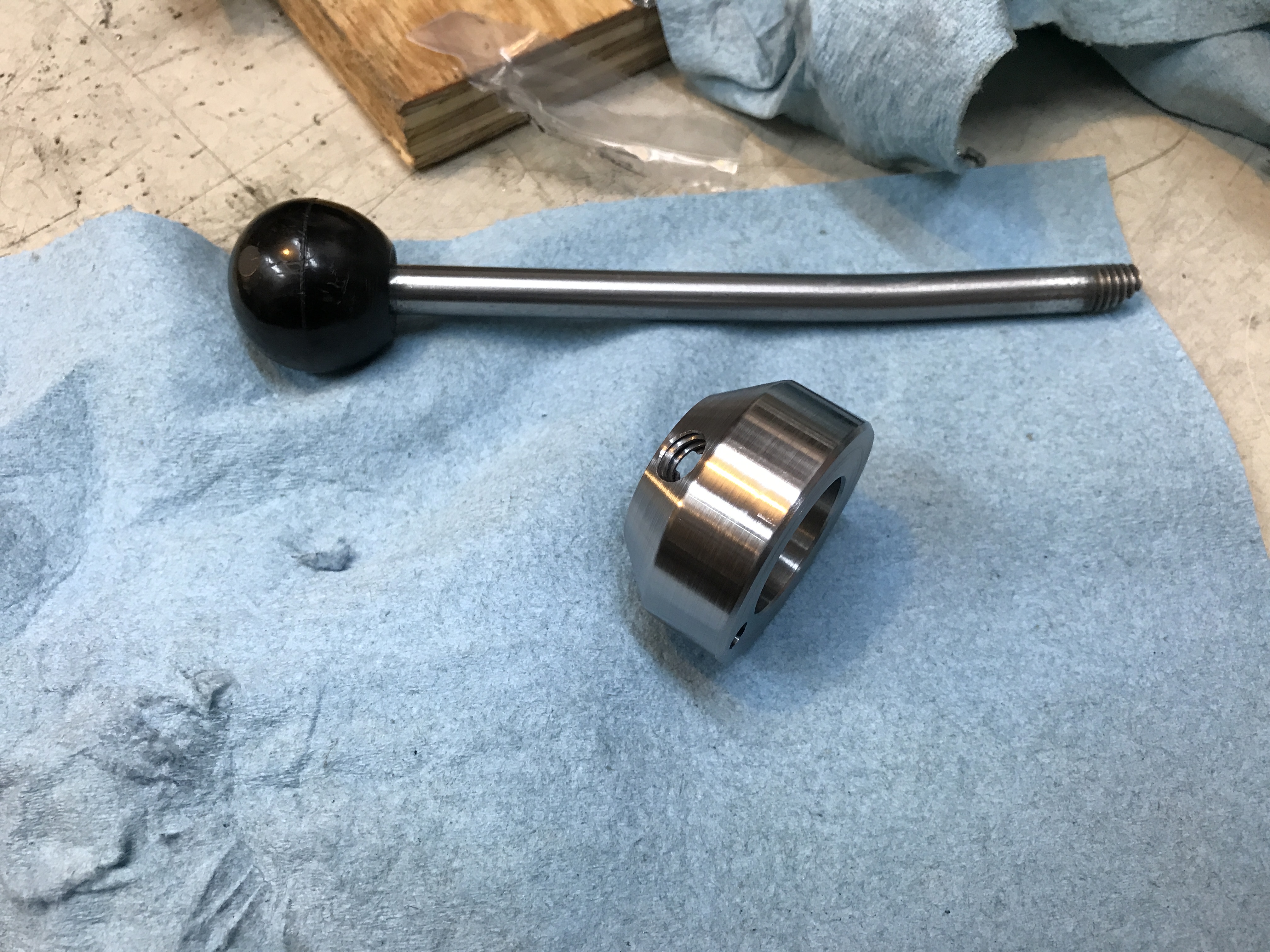
Blued parts assembled
Installed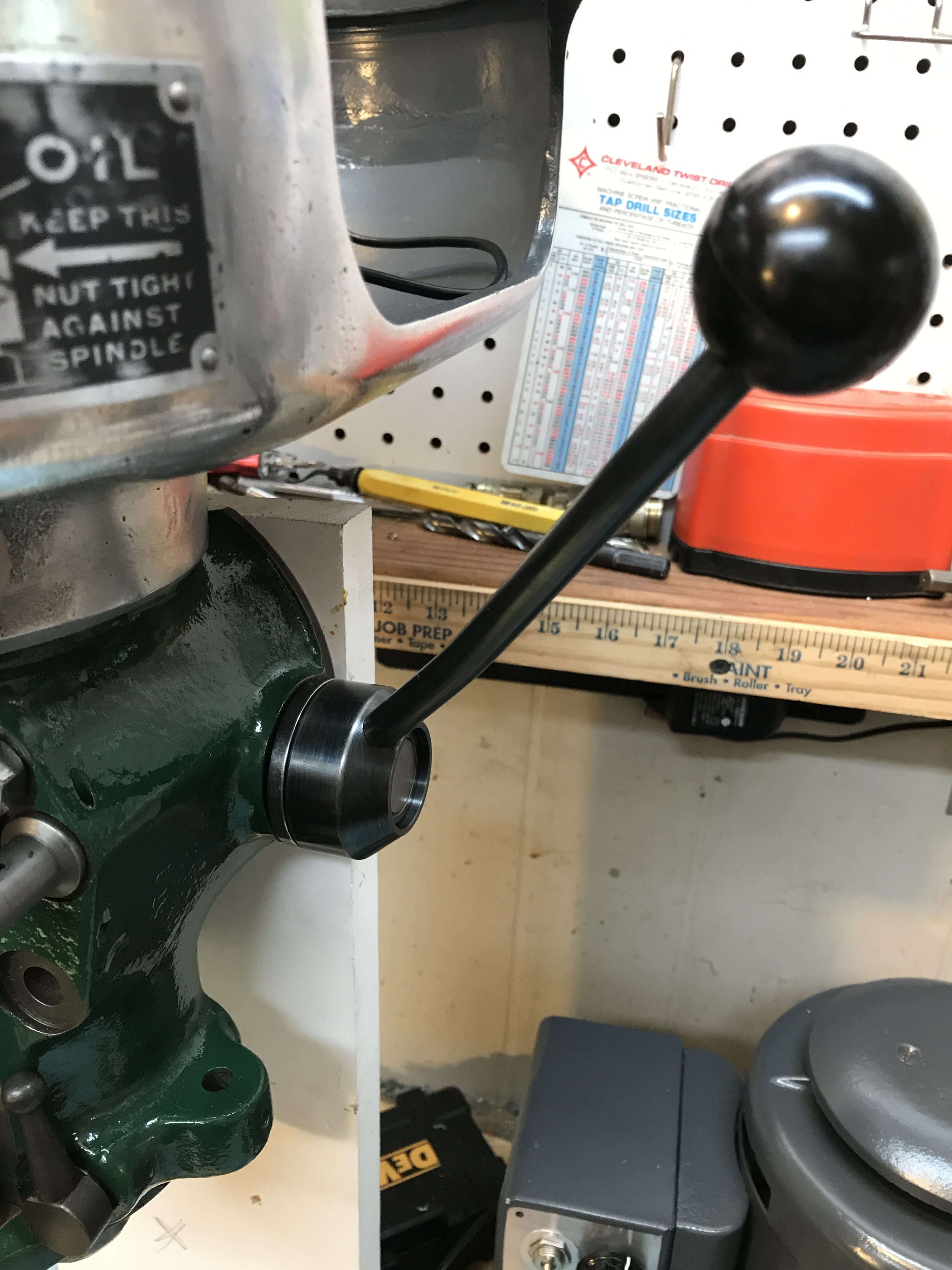
Column Risers
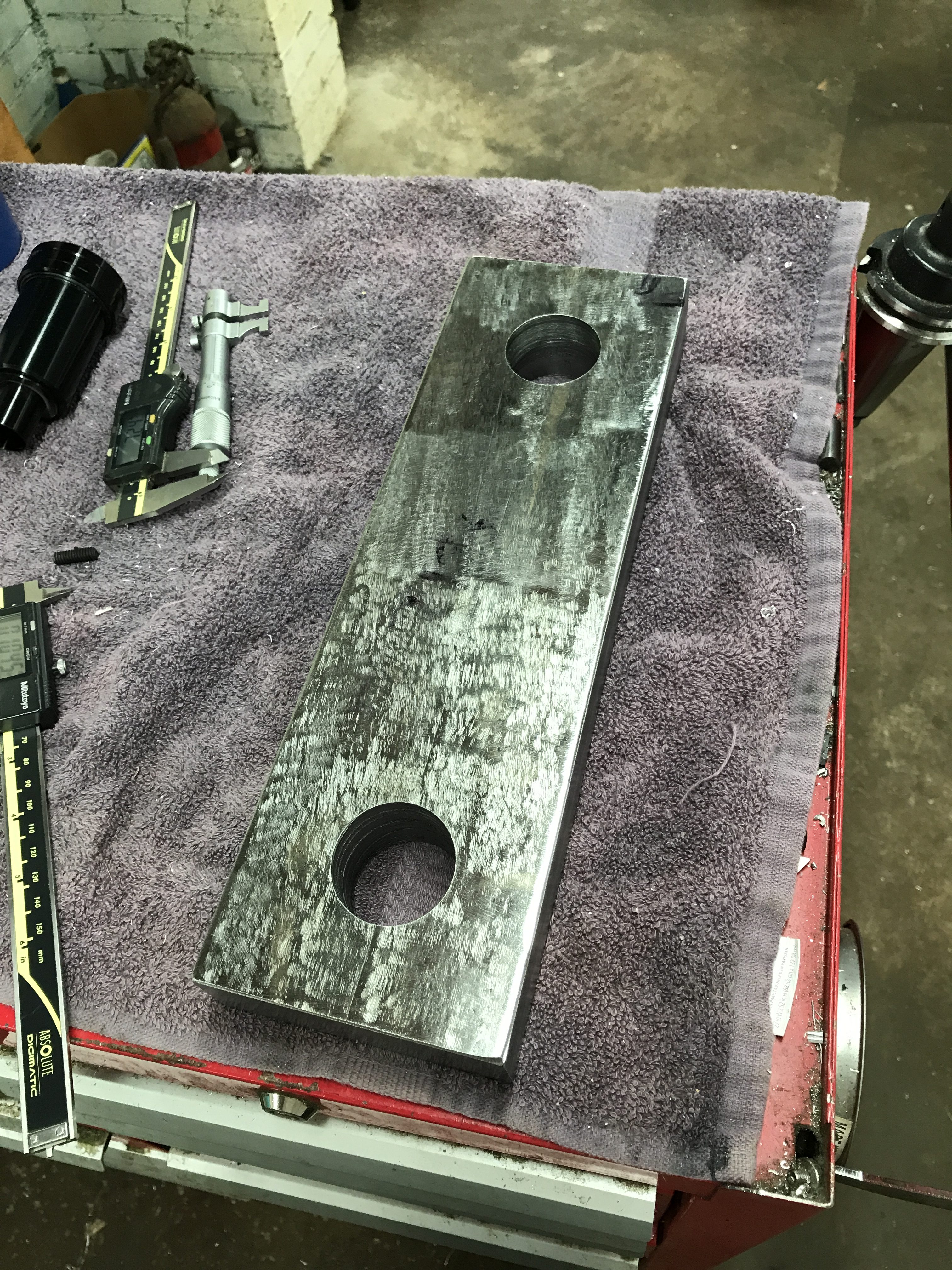
The column risers were an adventure to get done. I had to do all the work on them at a machine shop with a CNC mill in order to make sure the 2.5″ lower ram and 2.25″ upper ram holes were exactly the same distance from each other (9″ on center.) I used hot rolled steel because it was less than half the cost of any other steel option. Problems with hot rolled steel include a hard outer “skin” (which I removed with an angle grinder), inconsistent metal quality (found a hard deposit with an unfortunate 10-24 tap), and inconsistent dimensions. We worked around that at the shop and the risers turned out great. I painted with with the same Rustoleum hunter green color the BM and head are painted.
Two holes drilled on a manual mill first before going into the CNC
In the CNC mill
Using a slitting saw to cut the “squeeze” points (after drilling and tapping 1/2-13 threads)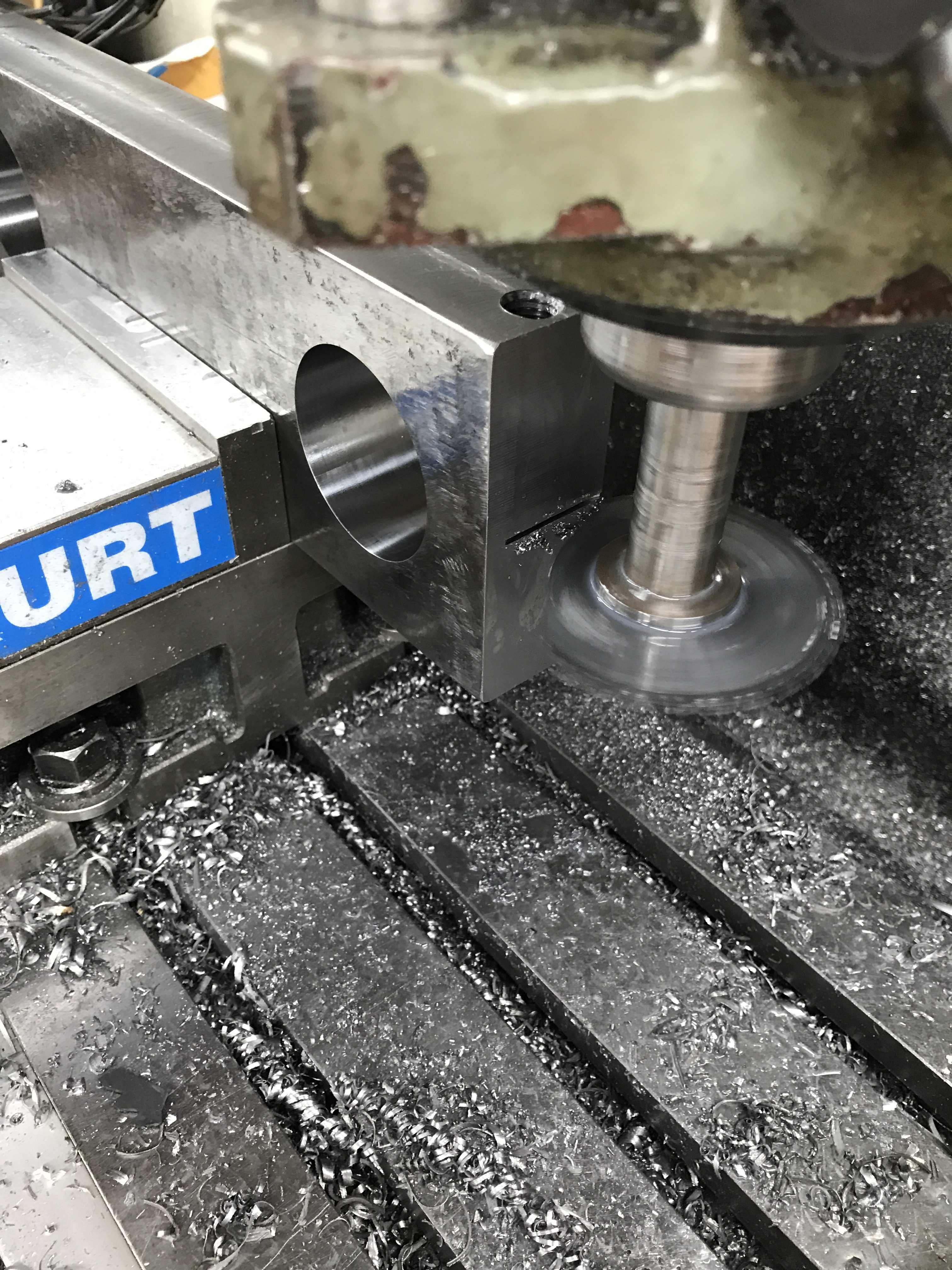
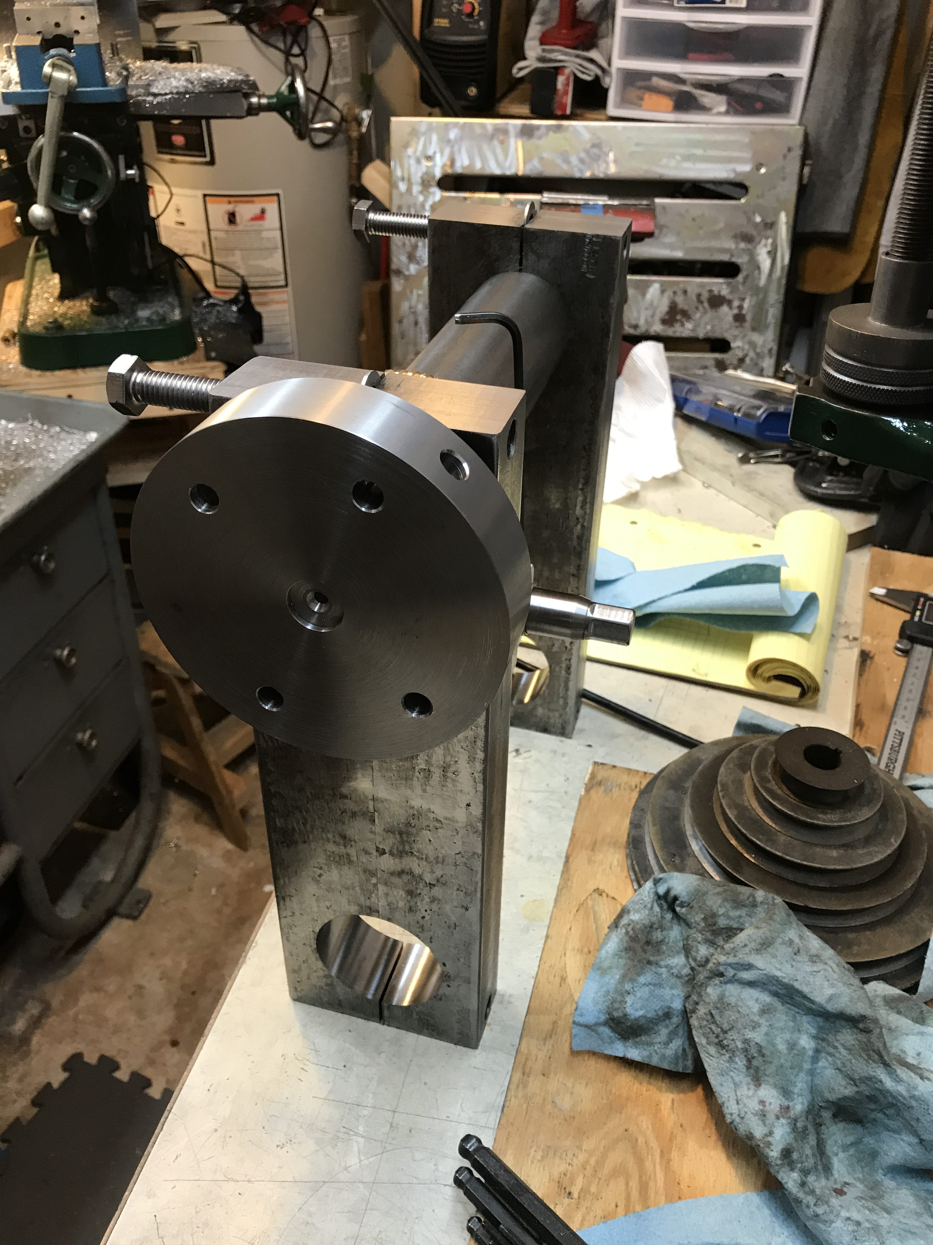
Pillow Blocks
I needed to make mounting blocks for the worm to connect with the worm gear. I bored the worm gear to 2.27″ (slip fit on the upper ram with a keyway).
Boring a press fit hole for a bronze bearing on the worm pillow block (using a boring head I picked up at an estate sale for $10!)

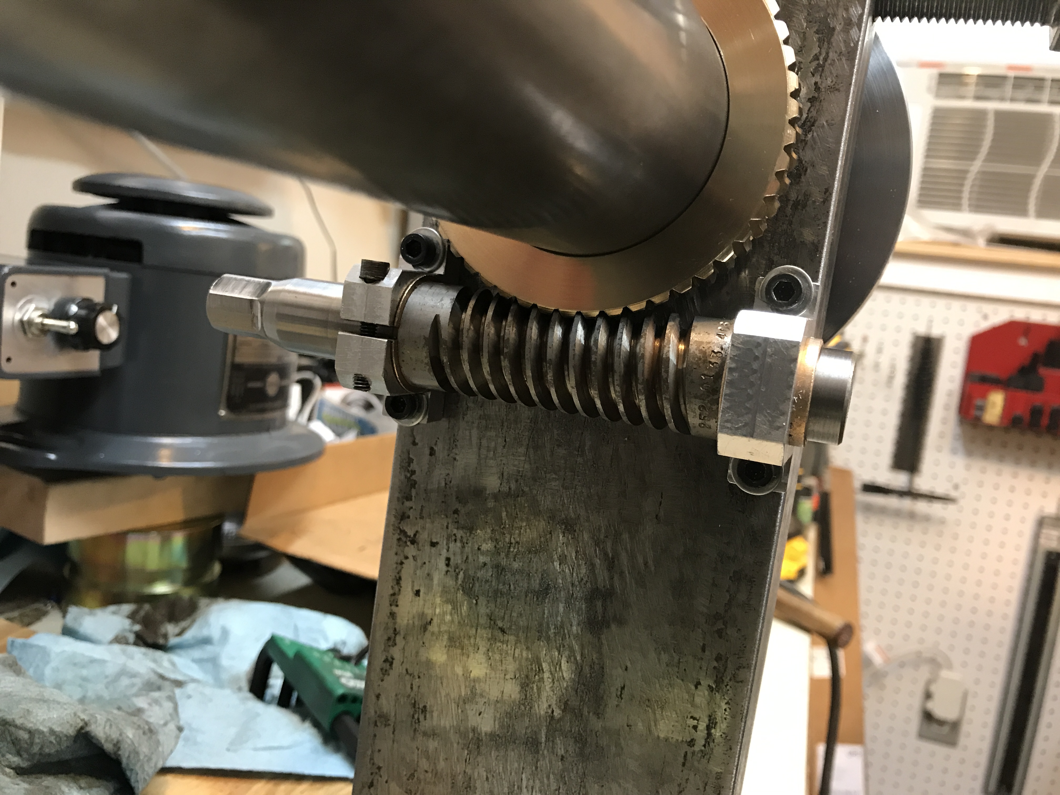
Cutting a head onto the worm
Cutting mounting slots (allows for small adjustments to the alignment of the worm)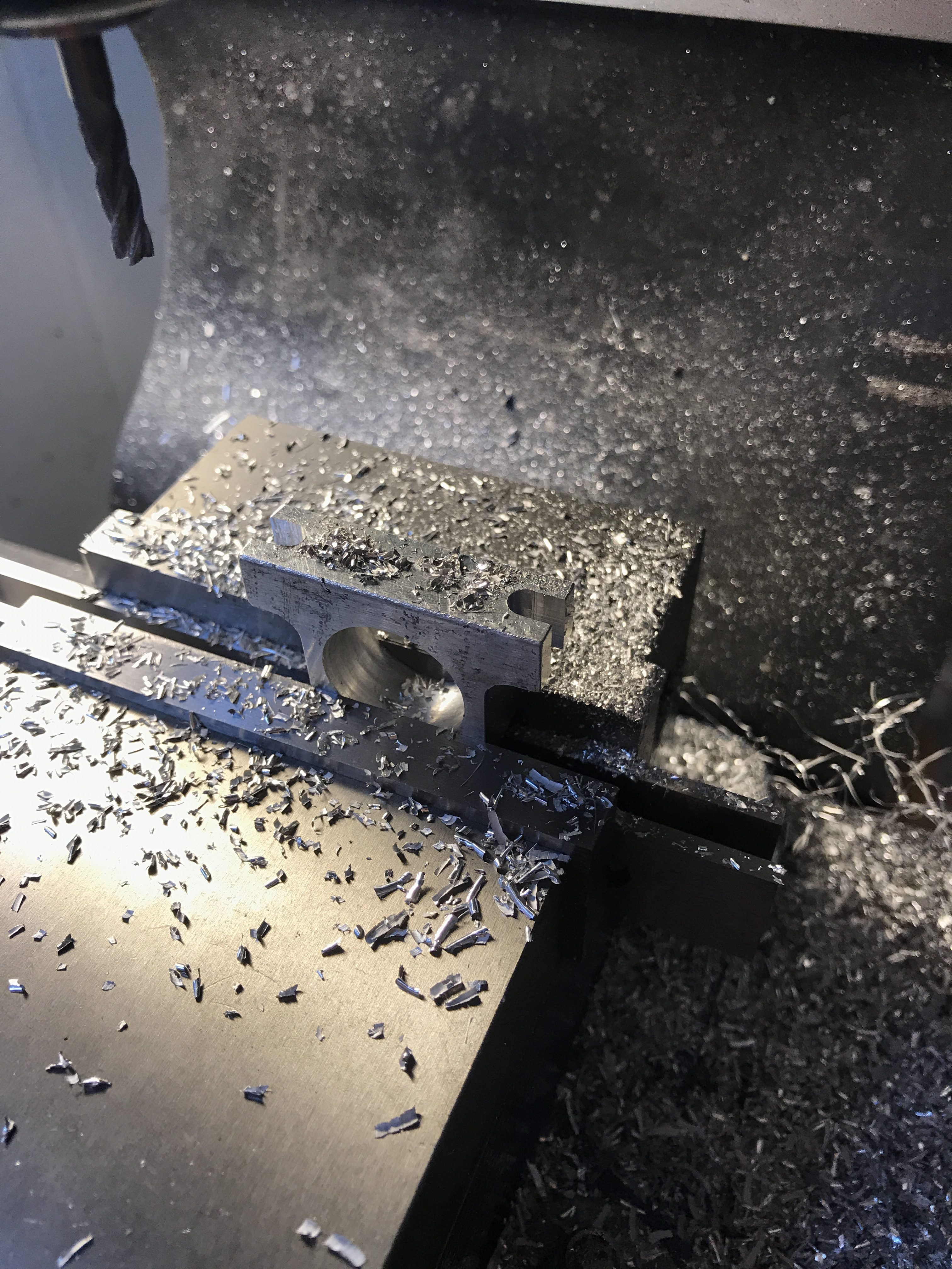
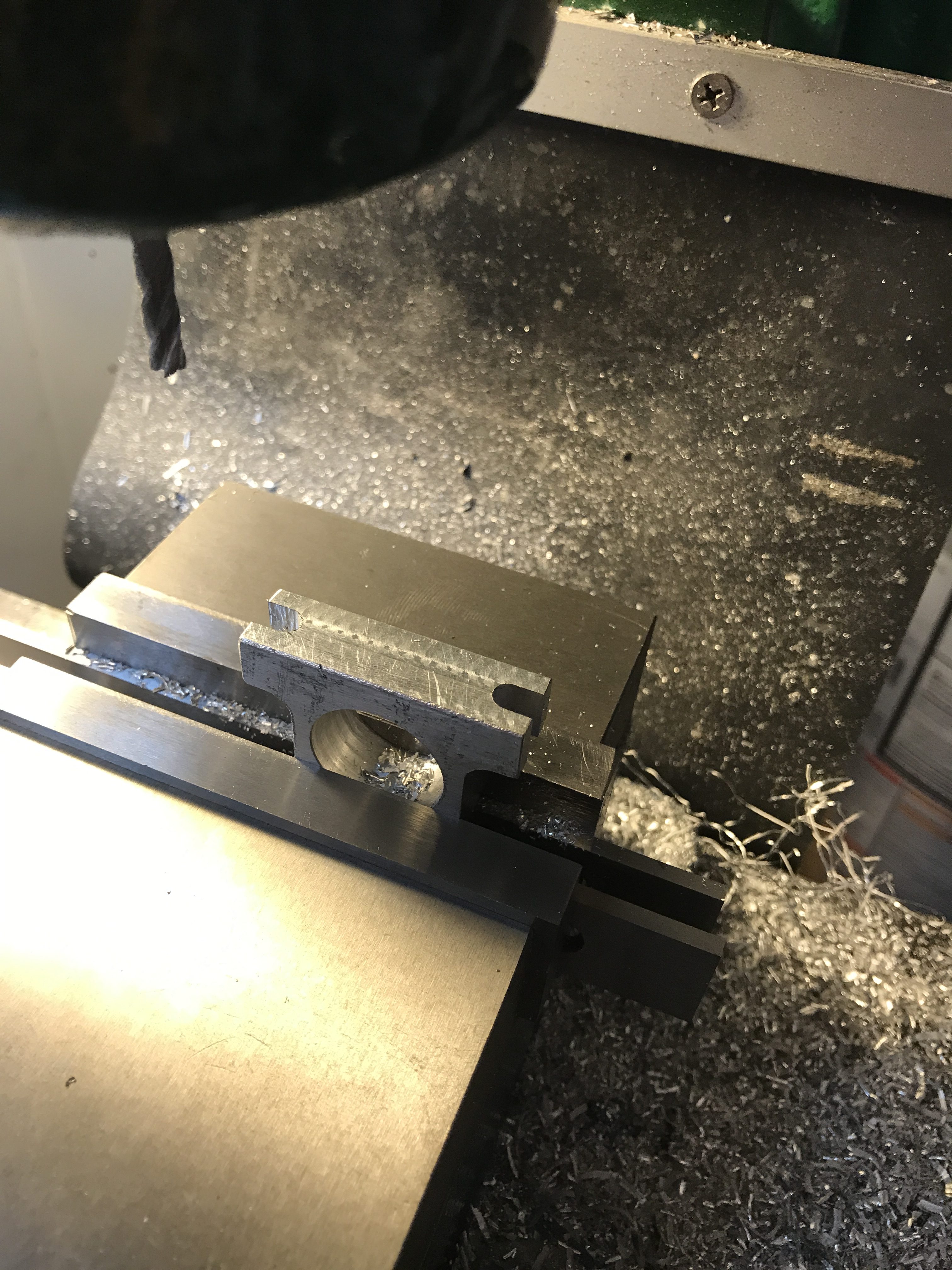
I cut a “squeeze” point into the pillow block and bronze bushing rather than making another locking device for the worm. This is just another small safety feature to make sure the mill head doesn’t spin if the bolts are loose for tramming.
Test fitting the riser columns and upper ram/flange
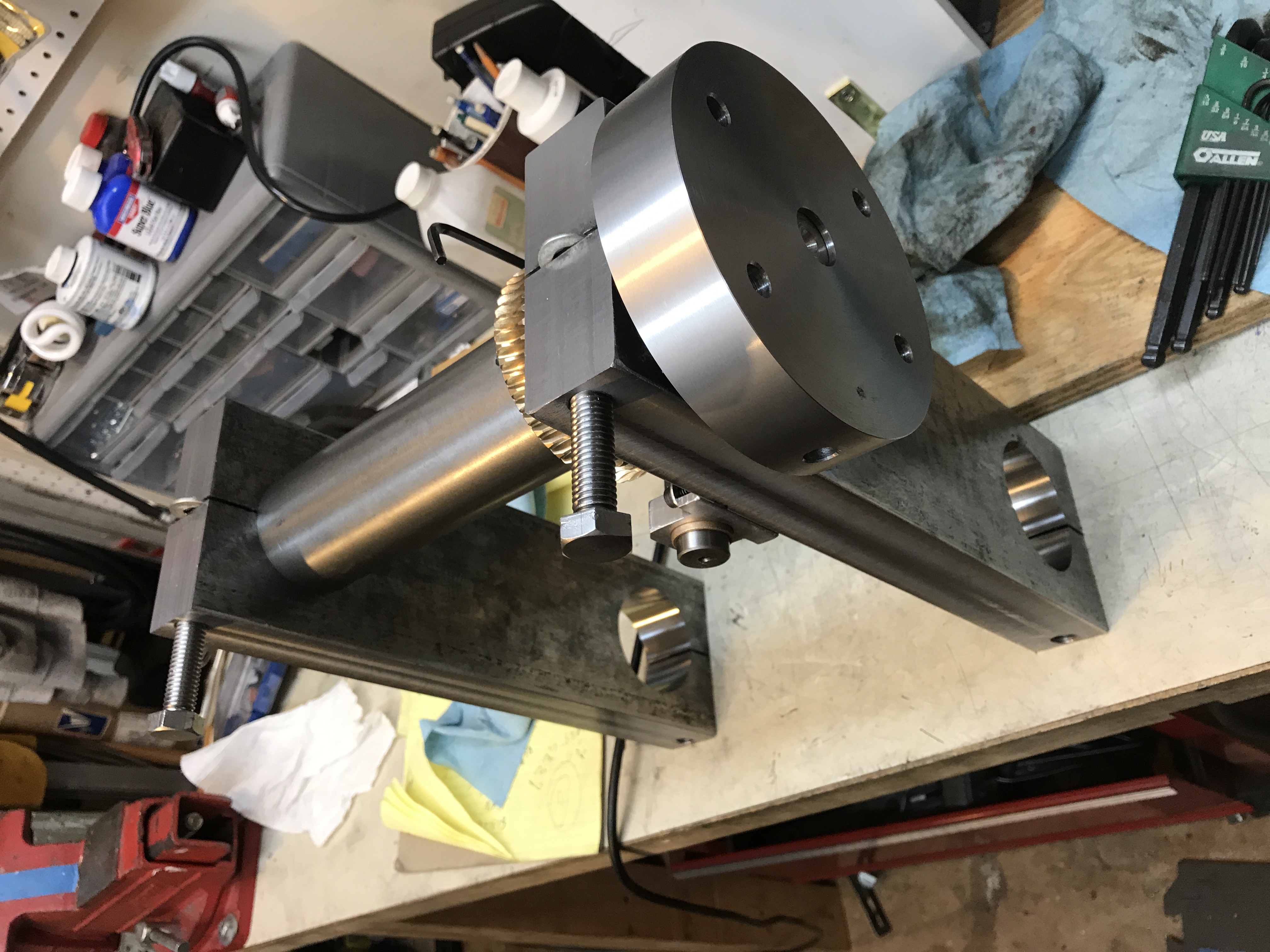
Using a worm gear allows me to make small adjustments to the head angle when tramming
After I test fit everything and was happy with the fit, I painted the riser columns and moved onto a few other tasks. While the paint dried, I moved things around my shop to accommodate the mill.
Facing the Flange
The upper ram needed to have the flange faced off on the lathe (which was machined separately and then press fit onto the ram along with some pointed set screws for added security). I had to get a steady rest for the lathe and was lucky enough to find what I needed with minimal effort to get it to usable condition.
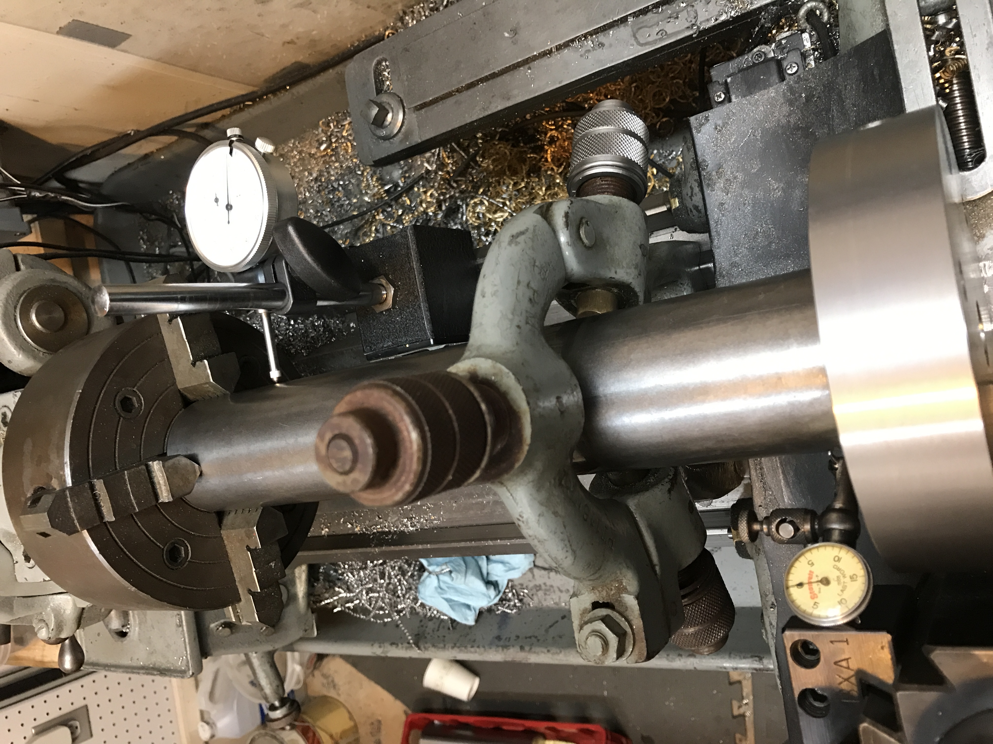
Using a 4-jaw chuck allowed me to dial in the ram to within .0005″ of being perfectly concentric when spinning. The second gauge (to the right) is to make sure the steady rest is aligned correct as well.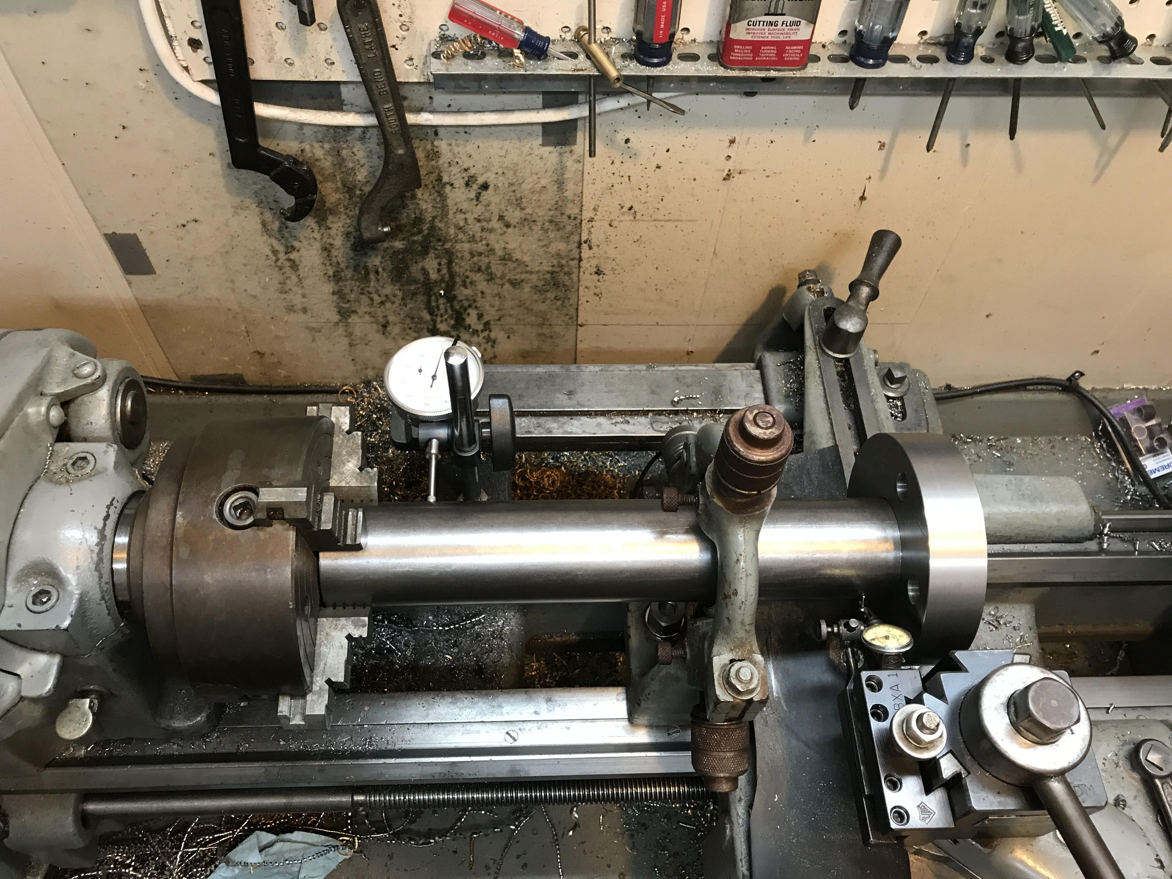
Facing the flange
I kept the gauges on the ram while machining to make sure there was no deflection when the tool was cutting. I had a .010″ deflection in one cut and had to correct the steady rest positions and got it to within .001″. I would have preferred .000″.
The finished upper ram and flange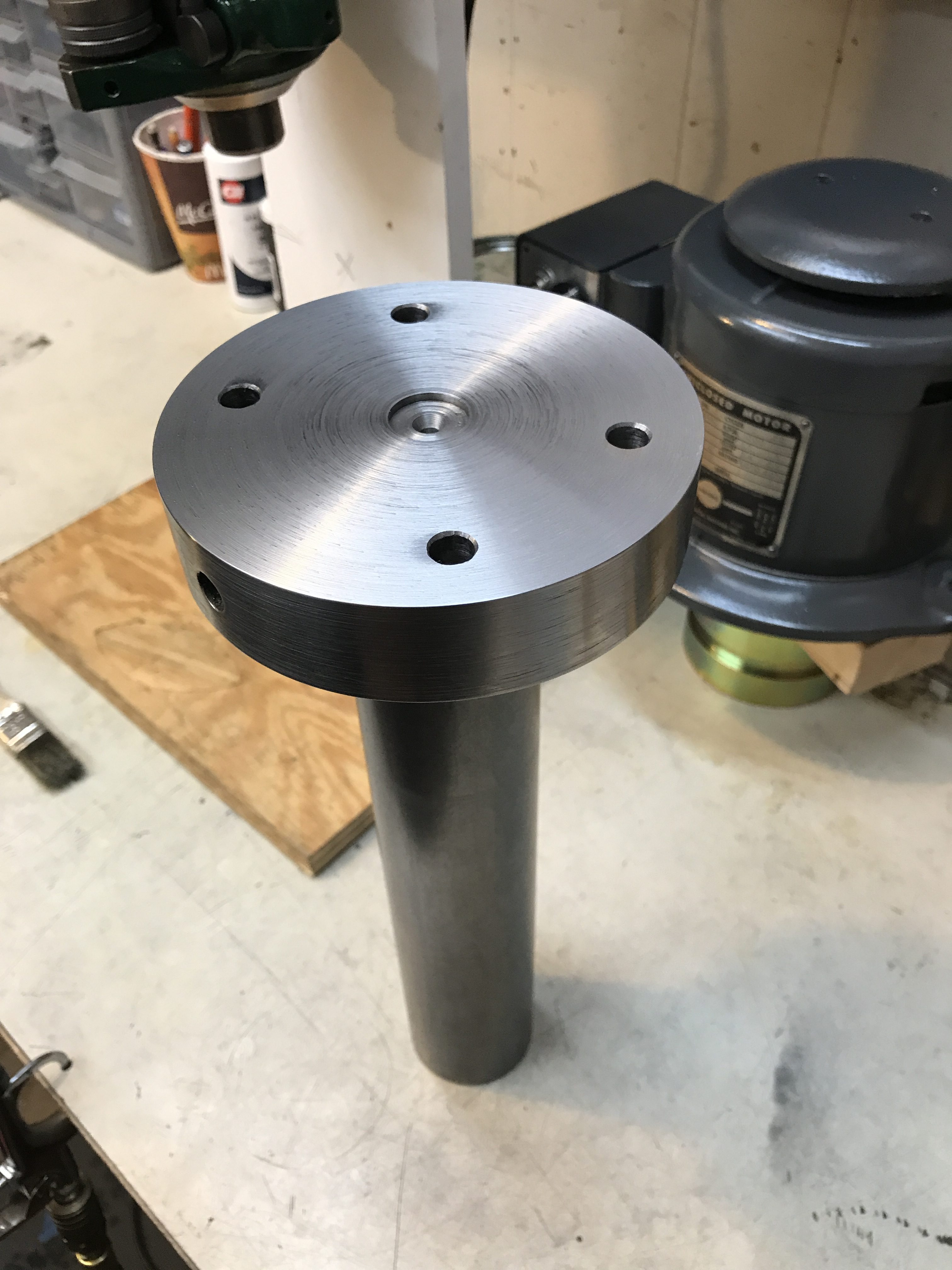

Almost Done!
I didn’t take photos when I was rearranging my (tiny) shop, but I moved the drill press off the bench (built specifically for this mill) and onto the bench that held the BM. I corrected a mistake I made when building the bench so that the “Steelmaster” storage files could fit properly around the knee screw. There are a few more photos that I’ve taken, but will save it for the final “installation and calibrating” post that will follow this.
Here is the current photo at the end of the day today: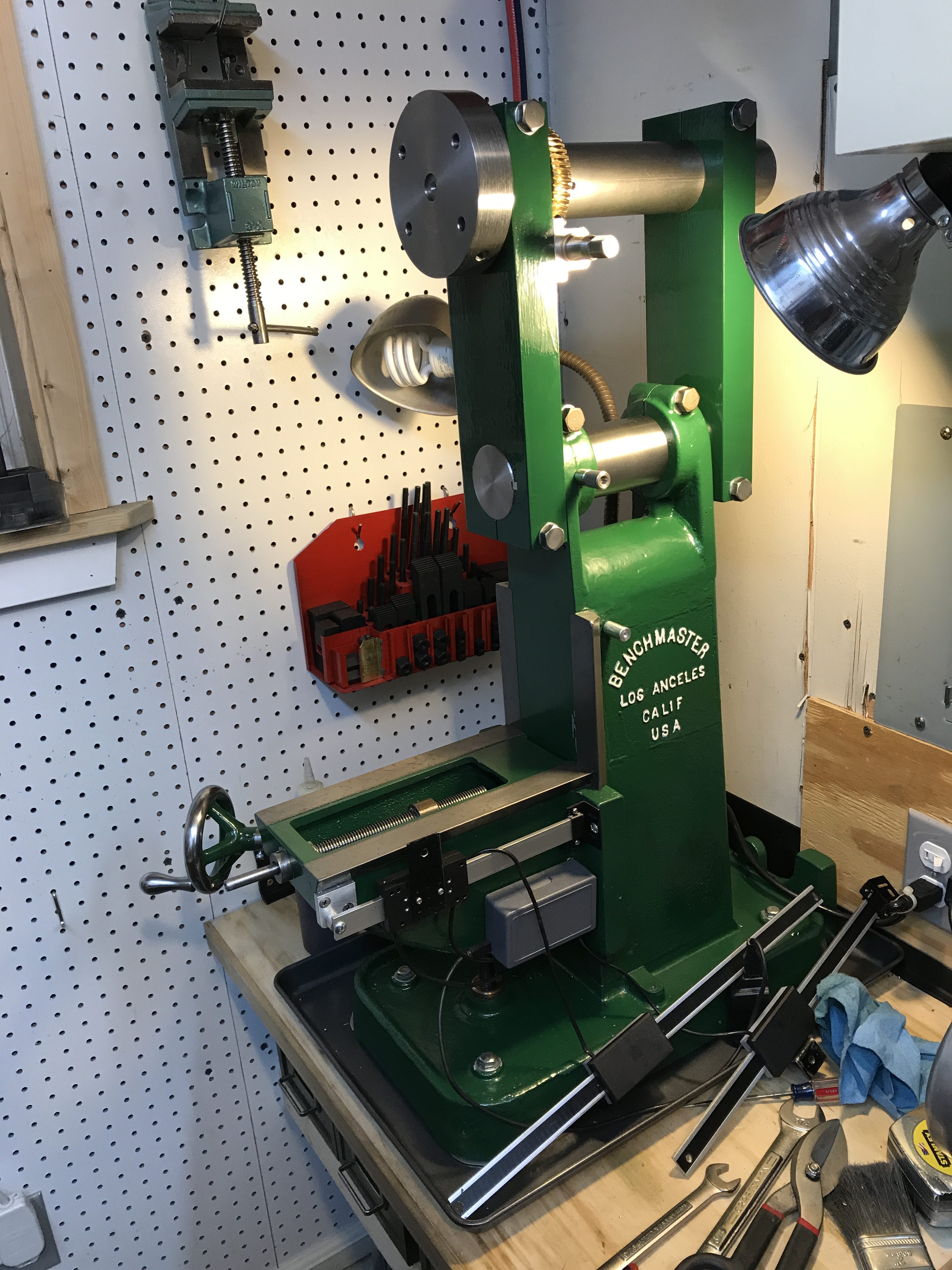
Leave a Reply