
Well school and the symphony are out for the summer, so I have time to continue working on this project. Since the last post, I rebuilt the quill and finished work on the pulley housing. I’ve started reassembly and planning for the mounting of the head.
The Quill
One of the primary reasons for marrying a Bridgeport M Head to a Benchmaster mill was the additional feature of a quill. A Rusnok head may be the most recommended option, but not only did I lose the one eBay auction I tried to get one through, I figured the additional quill travel of the BP was better. Plus everywhere I read, it’s said it won’t work out. I take that as a challenge and plan to make it work perfectly fine…
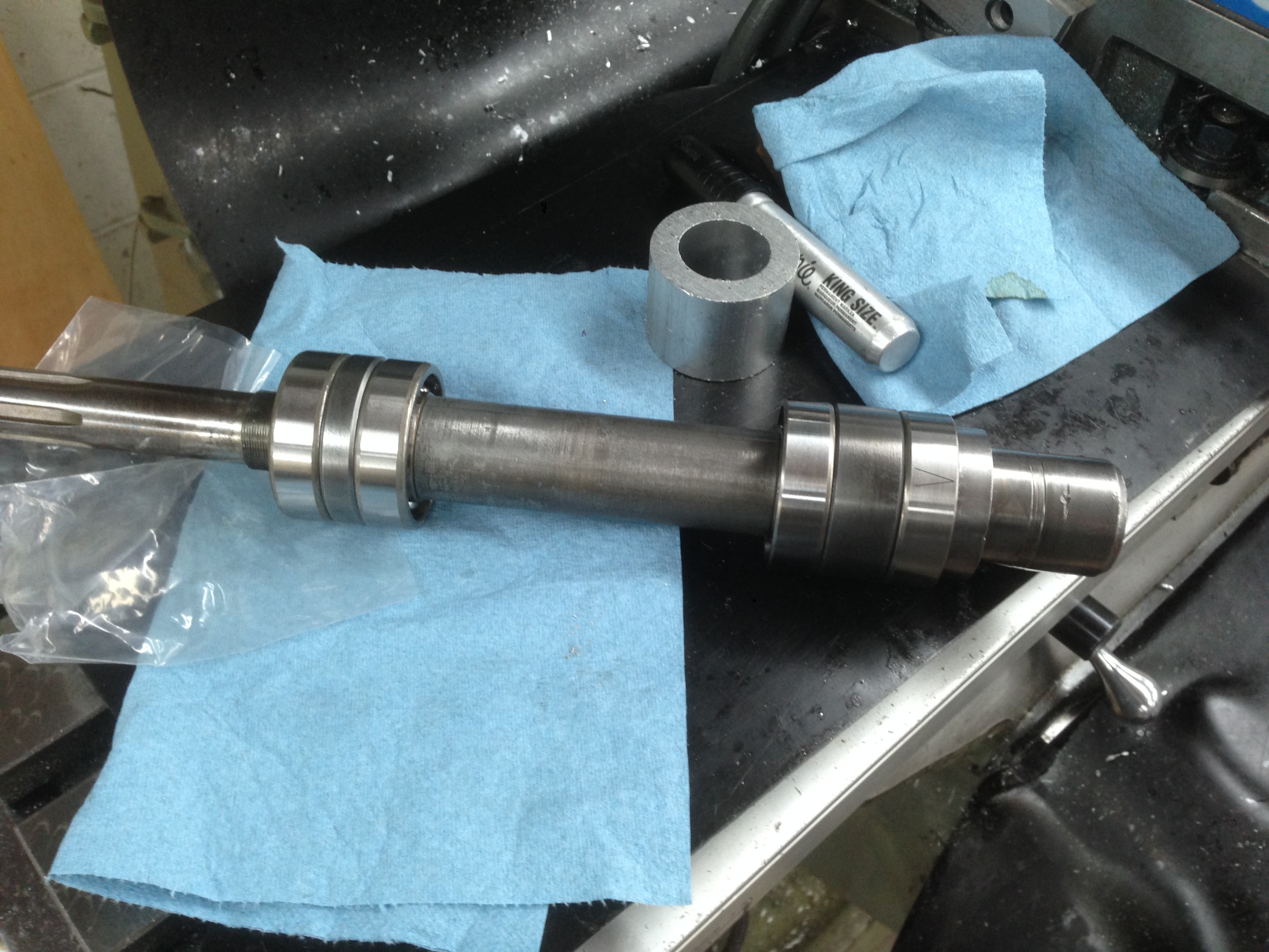
The bearings I purchased for the quill and pulley spindle are listed in the other parts of this “series” I have going here. Installing the bearings was easy following directions found online. I headed to my machinist-friend’s shop where he has a nice large Dake arbor press and bunches of scrap metal that made perfect pieces for pressing the bearings on from the correct spots.
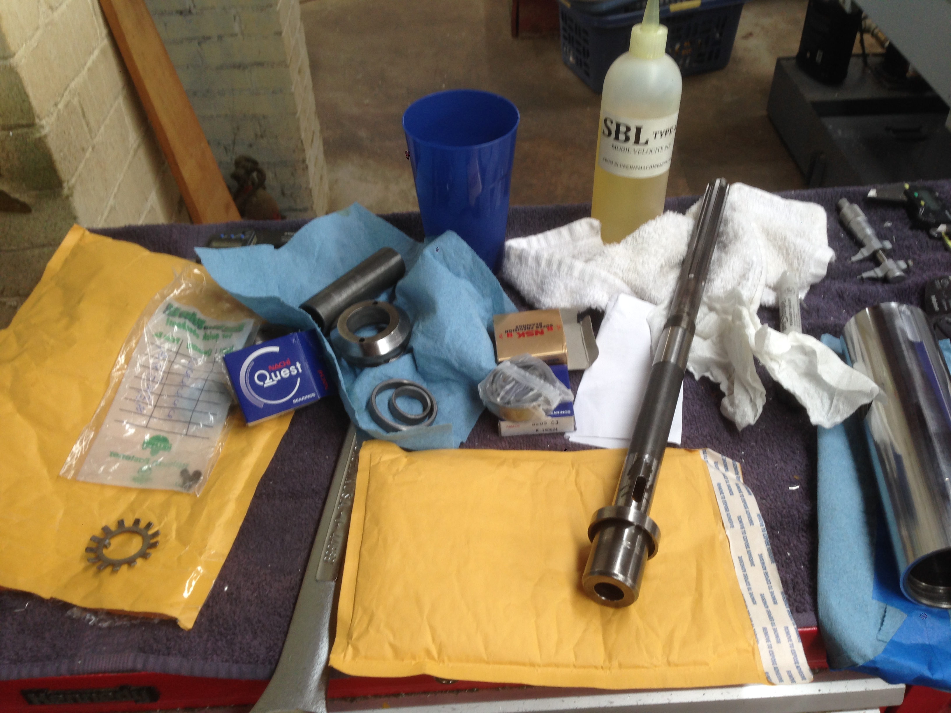
The spacers inside the quill need to be perfectly parallel and even for each double set of bearings, and lucky for me the spacers were just that. I cleaned them up on a surface plate with some emory paper and checked them with a .0005″ indicator and saw no movement on the needle for the lower (critical) set. The upper set had a burr or two on the spacers that had to be removed (again, emory paper), and though parallel, the spacers had less than .0005″ difference between them. Not enough to worry about since these are the upper bearings, and after tightening down the preload on them, they didn’t rattle or move.
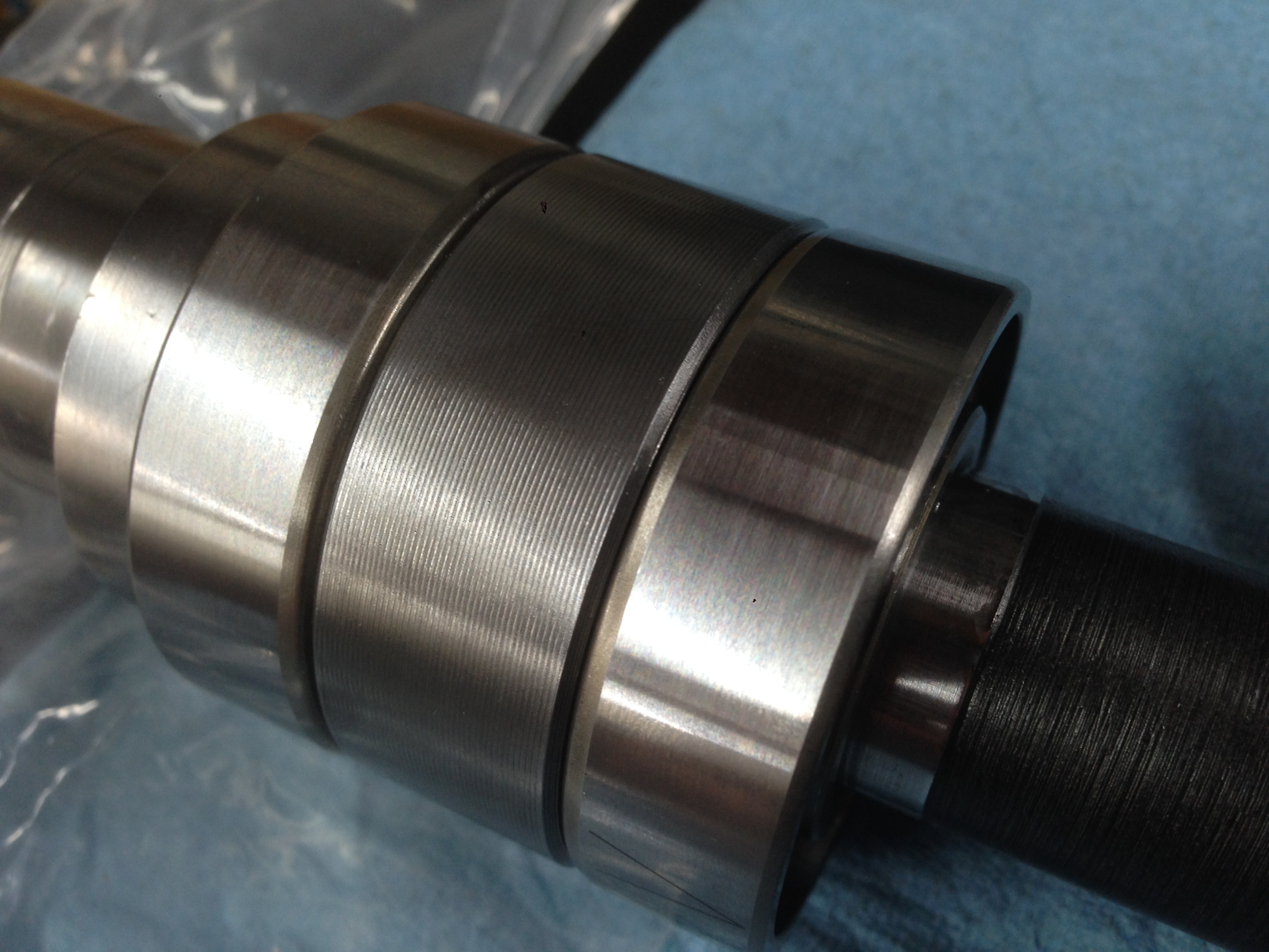
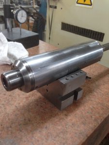
Using a .0001 indicator reading multiple locations inside the Morse Taper #2 spindle, the quill bearings were set up with preload to a max .0002″ runout. According to the machinist it was likely closer to .00015″. My goal was .0003″ so I’m happy about nearly cutting that in half. Once the quill is installed in the head and motorized, I’ll use some emory cloth to clean up the inside of the taper.
The Head Casting
I chose to match the paint color I used (Rustoleum green) on the head casting and skip primer or casting filler. I’ve found paint tends to dry a bit harder without primer on cast iron, but that’s just my experience. Also, when transitioning to bare cast iron, I hate seeing the primer color sticking out. If the head needs repainting in the future, I may opt to use filler as the casting is a bit rough, but hey, so is my BM and South Bend lathe (from the WWII years.)
Before:
After: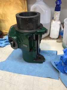

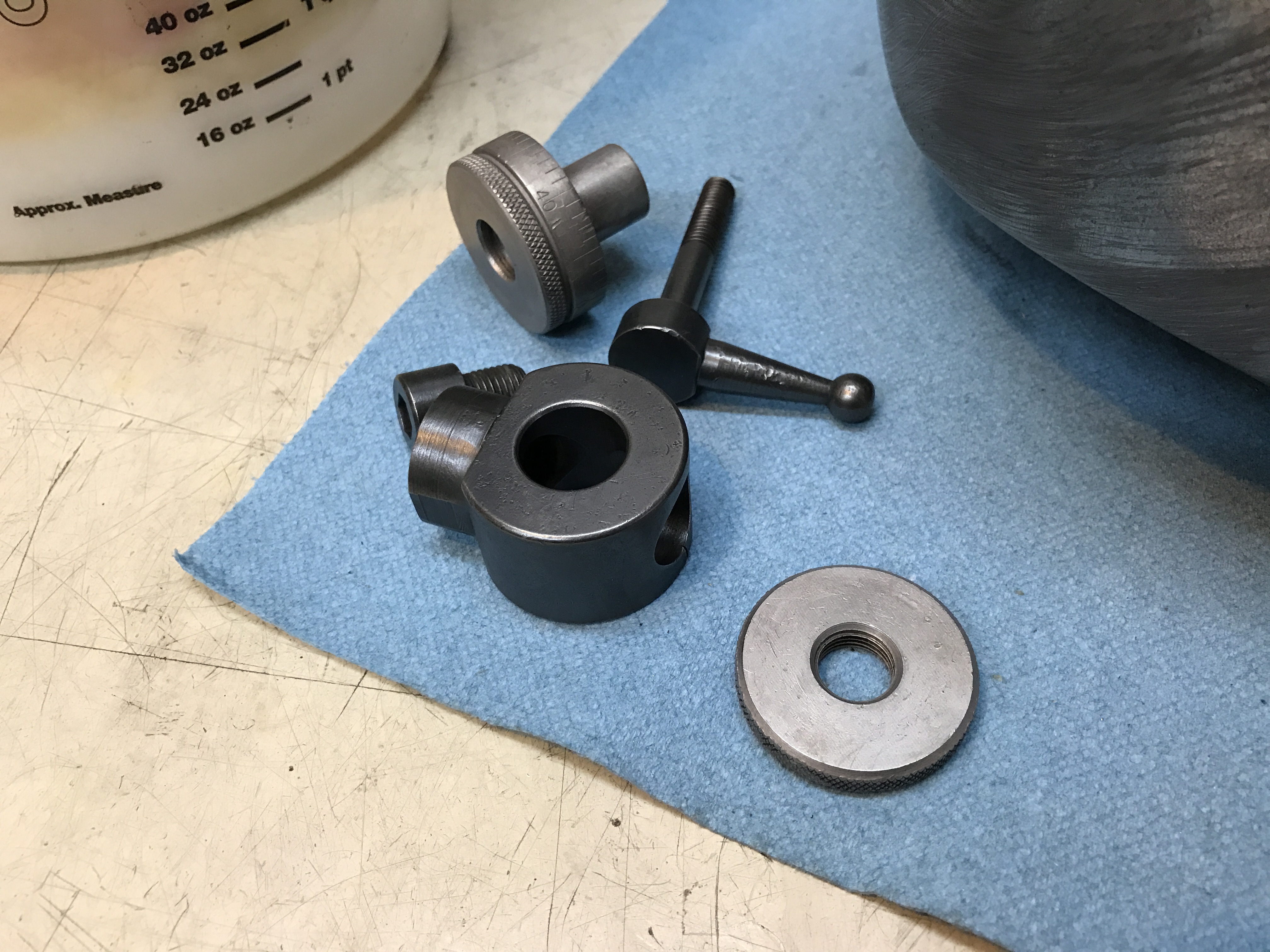
Once I was ready to reassemble the head, I polished the metal parts and used a cold bluing kit to get something close to the original BP black finish. I think things turned out well.
The Pulley Guard
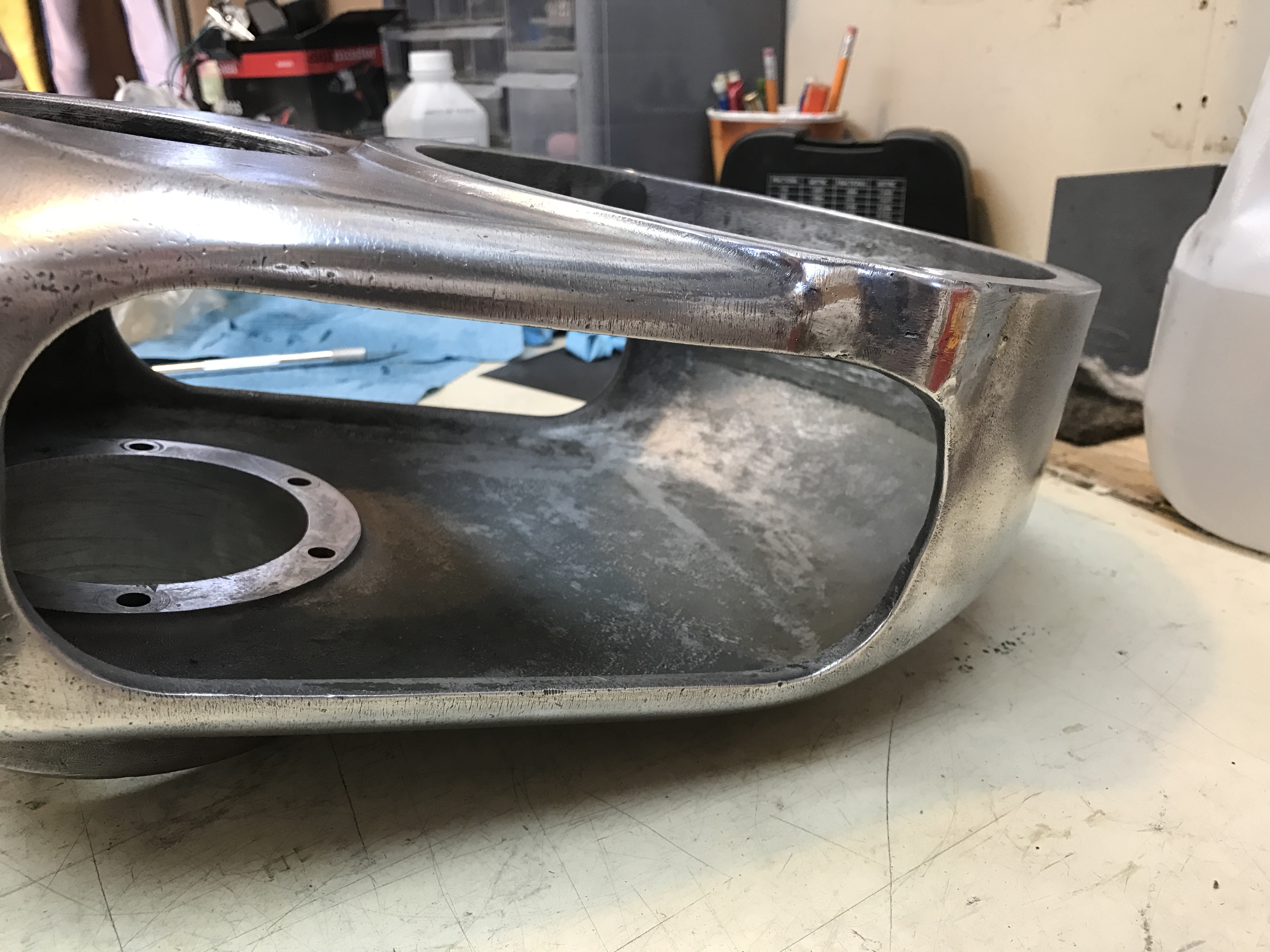
I’ve progressed through finer and finer grits of steel wire brushes, sanding flaps, and various other abrasives attached to a bench motor and finally moved onto hand sanding. Next up will be the buffing wheel and compounds, and Gord’s Aluminum Polish as a final step. I painted the inside of the casting before using the Gord’s. I’m not sure if it was originally painted, but it will make it easier to clean out slung oil from the pulley bearings.
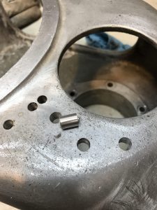
Filling holes:
Holes filled before surface finishing: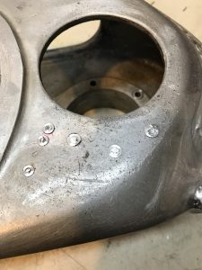
Moving up through grits:
Starting to get shiny again:
Ready for buffing: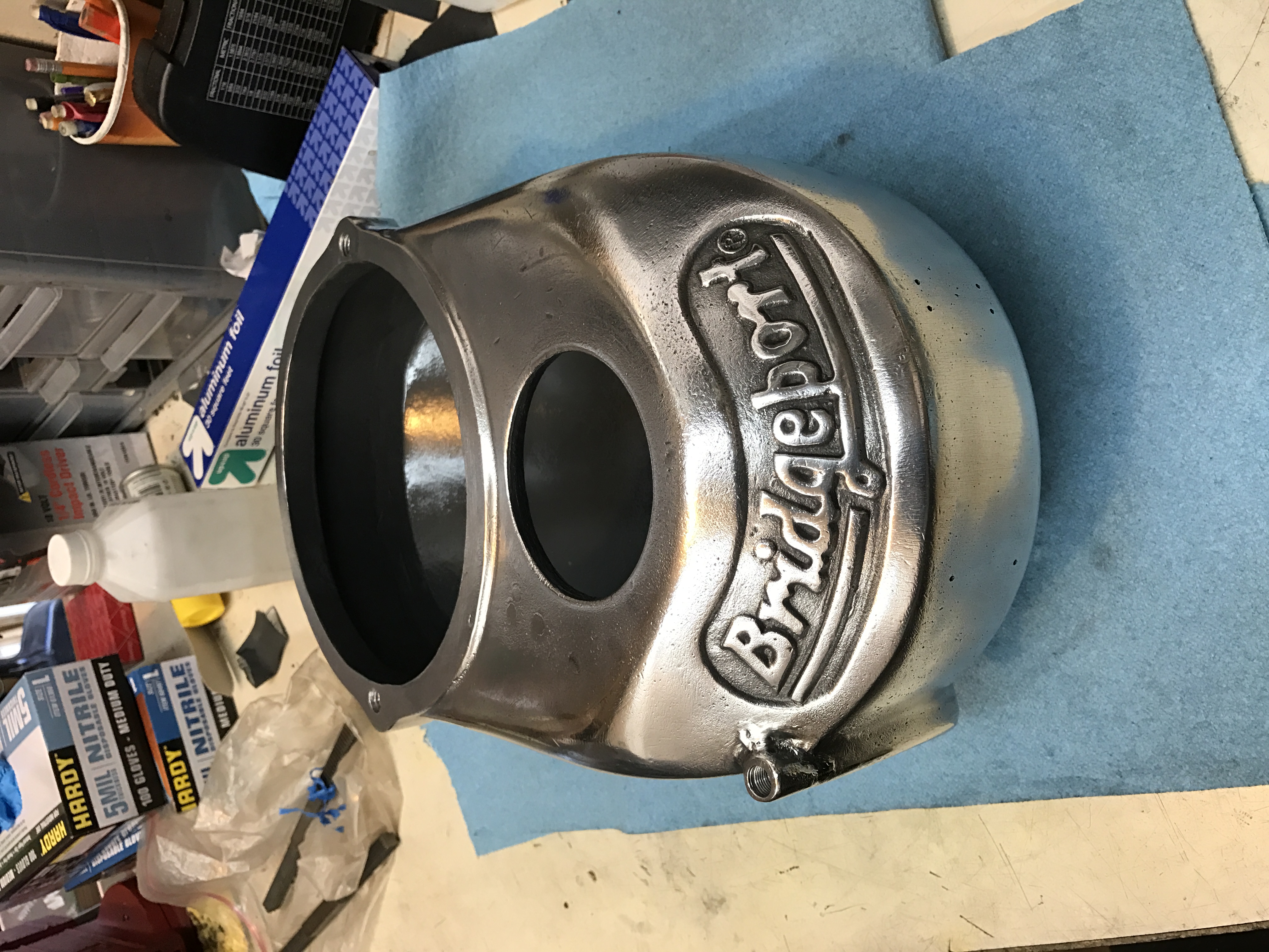
Buffing stage:
Inside painted: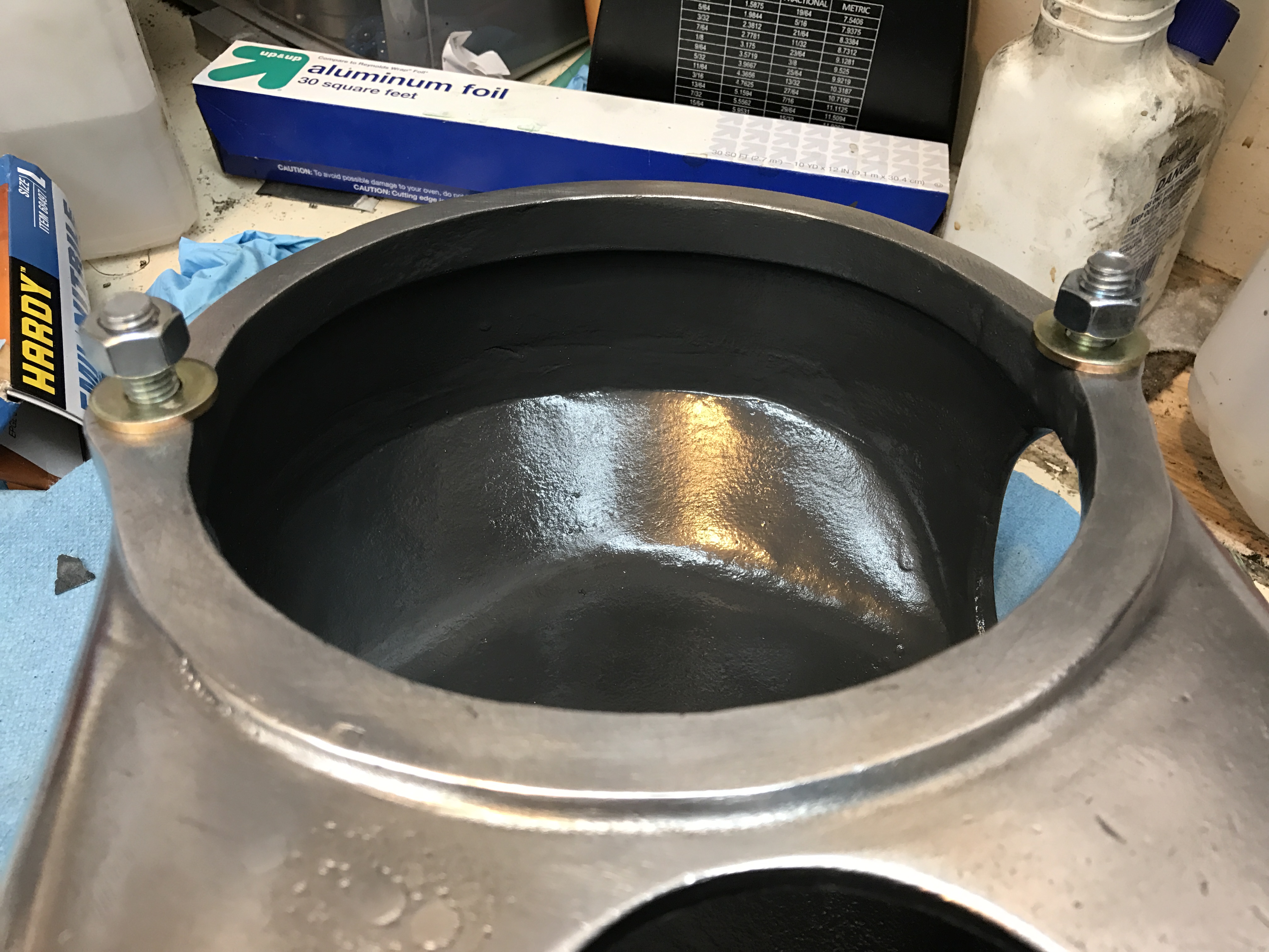
Repairs barely visible: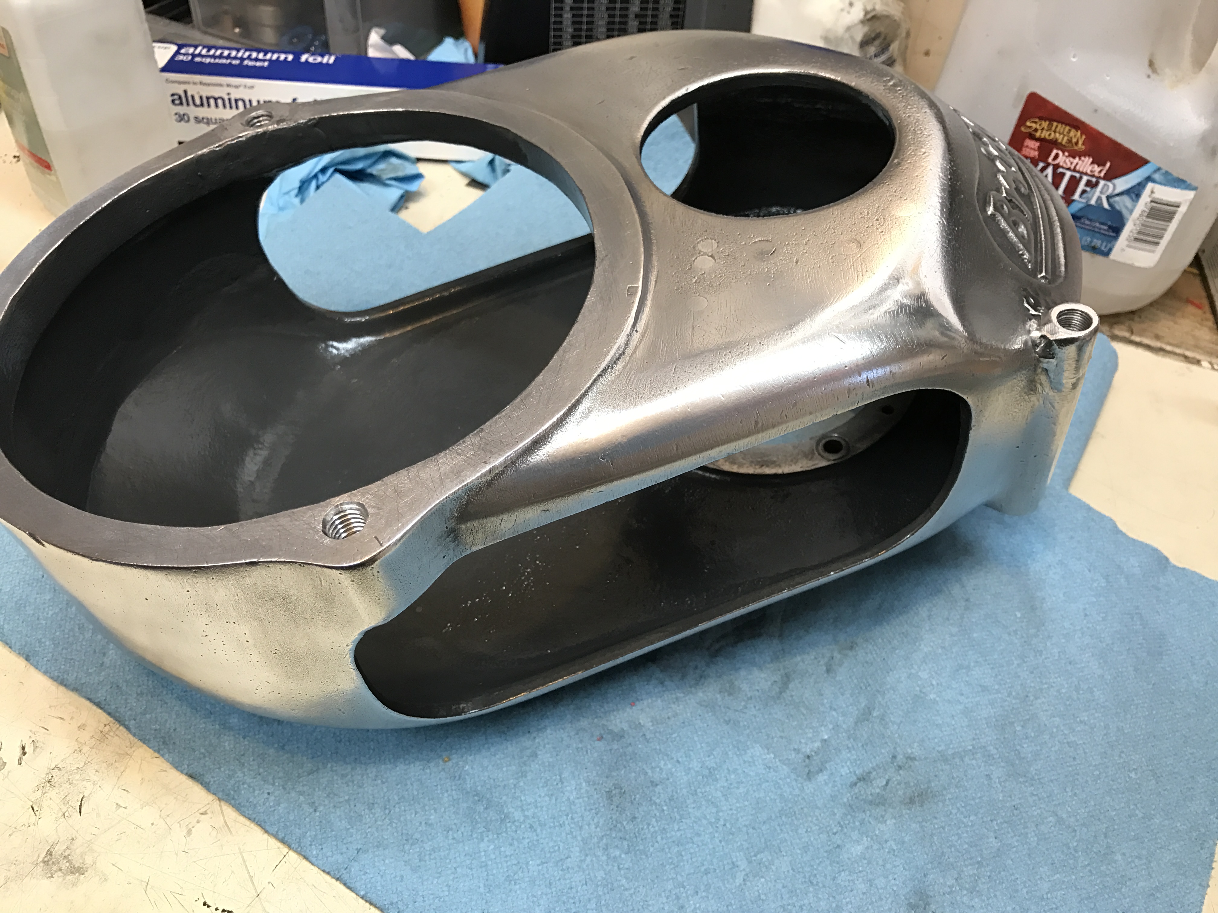
Painting the sunken area of the logo:
Installing the paper gasket under the spindle pulley bearing housing:
Making the gasket was a rough adventure…
Spindle pulley bearings installed:
Spindle pulley bearing housing installed, with gasket: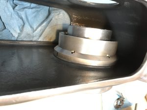
Finished: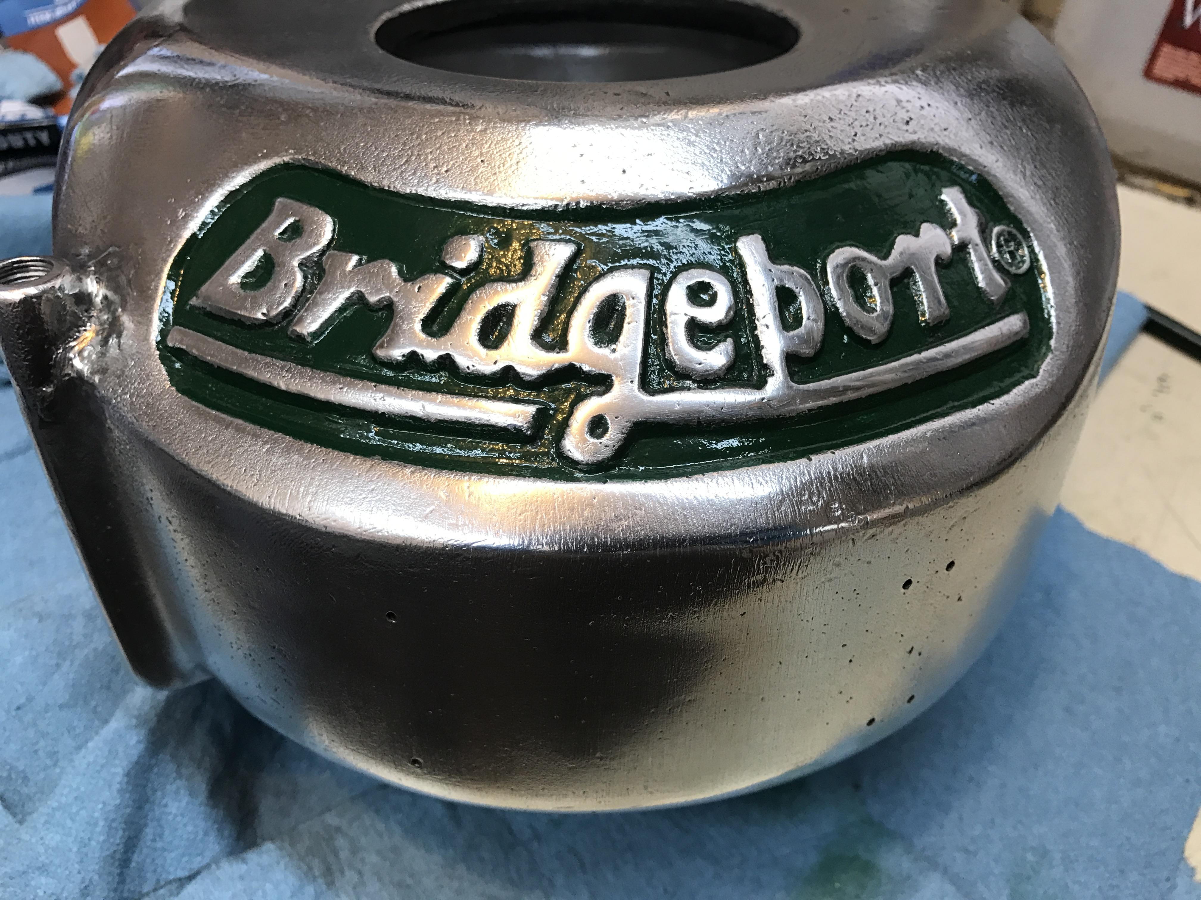
The pulley housing will never be perfect but it’s far better than the way it came!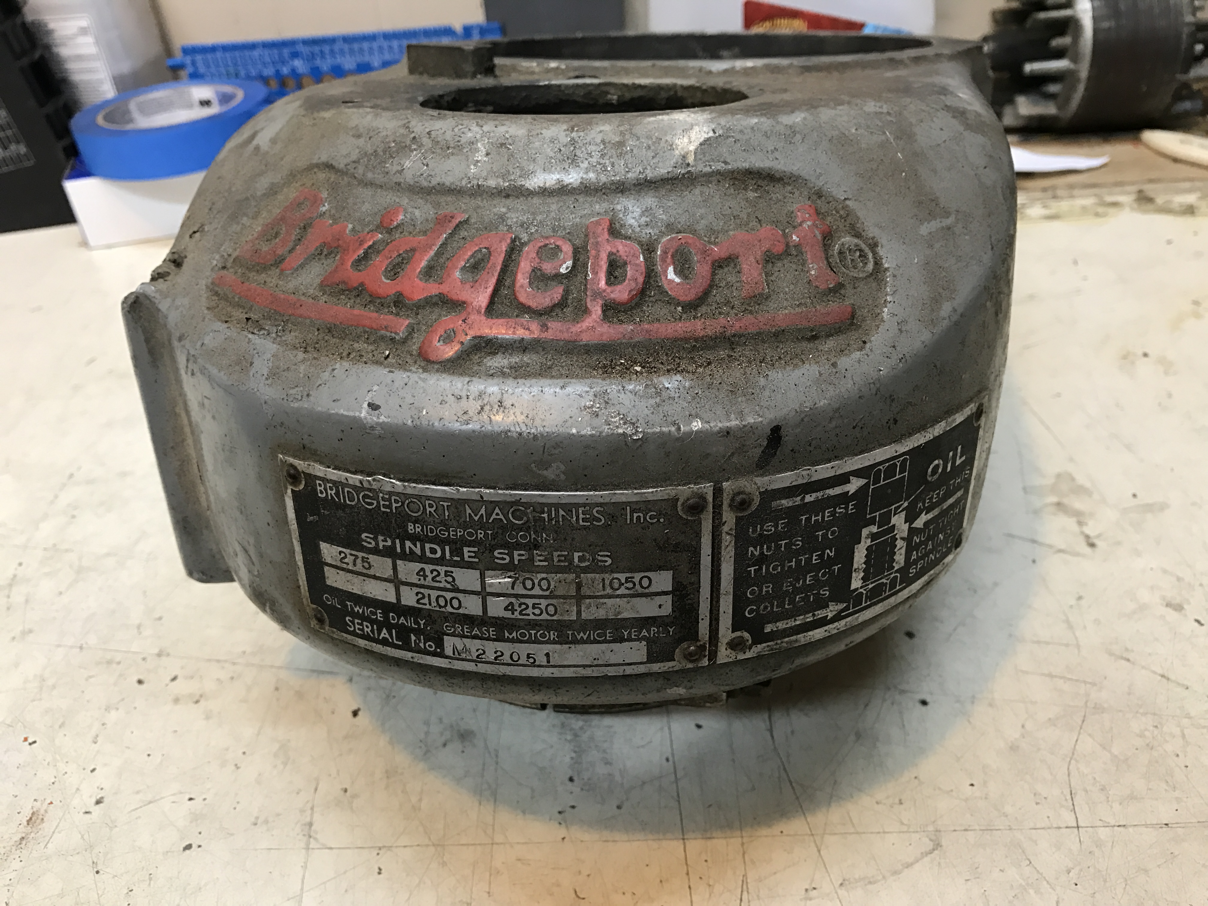
The Motor
Some pictures of the assembled motor. The original switch box will house the VFD’s potentiometer and power switch.
I used brass tacks Loctited into place to replace the original tag rivets:

Since this photo was taken, I reversed the side the housing is on so I can use my left hand to control motor direction and speed (and my right to operate the quill for power tapping.)
Mounting Ideas
I’ve been brainstorming ideas to mount the head to the Benchmaster. The first idea most people doing this would consider is simply mounting the head to a round ram in the BM’s casting. However, that won’t leave much (if any) room to work with tooling and parts. I plan to build two identical risers with mounting holes for the 2.5″ diameter ram that will go directly onto the BM’s casting and a slightly smaller ram above that. I’m thinking of using a 2″ diameter, but may opt to go 2.5″. The lower ram will be pinned into the casting to keep it from spinning, and the upper ram will be keyed to allow it to move back and forth, effectively increasing the working envelope of the Y travel. I plan to use a 9″ center to center spacing for the lower and upper rams, increasing the “daylight” between the BM’s table and the spindle bore.
I’m debating using a worm gear for tramming the head. I feel like it would be a good idea and a safety feature to keep the head from falling over while tramming.
There is still plenty to figure out with the mounting ideas, but I’m confident my idea will work. I’m sure it will take a lot of machining at the full machine shop, too…
The head as it sits as of this post:
The pulley housing isn’t tightened and will come off once or twice more as I work on a power drawbar idea. I dare not mount the motor as the temporary stand holding this all up would surely snap under the combined weight.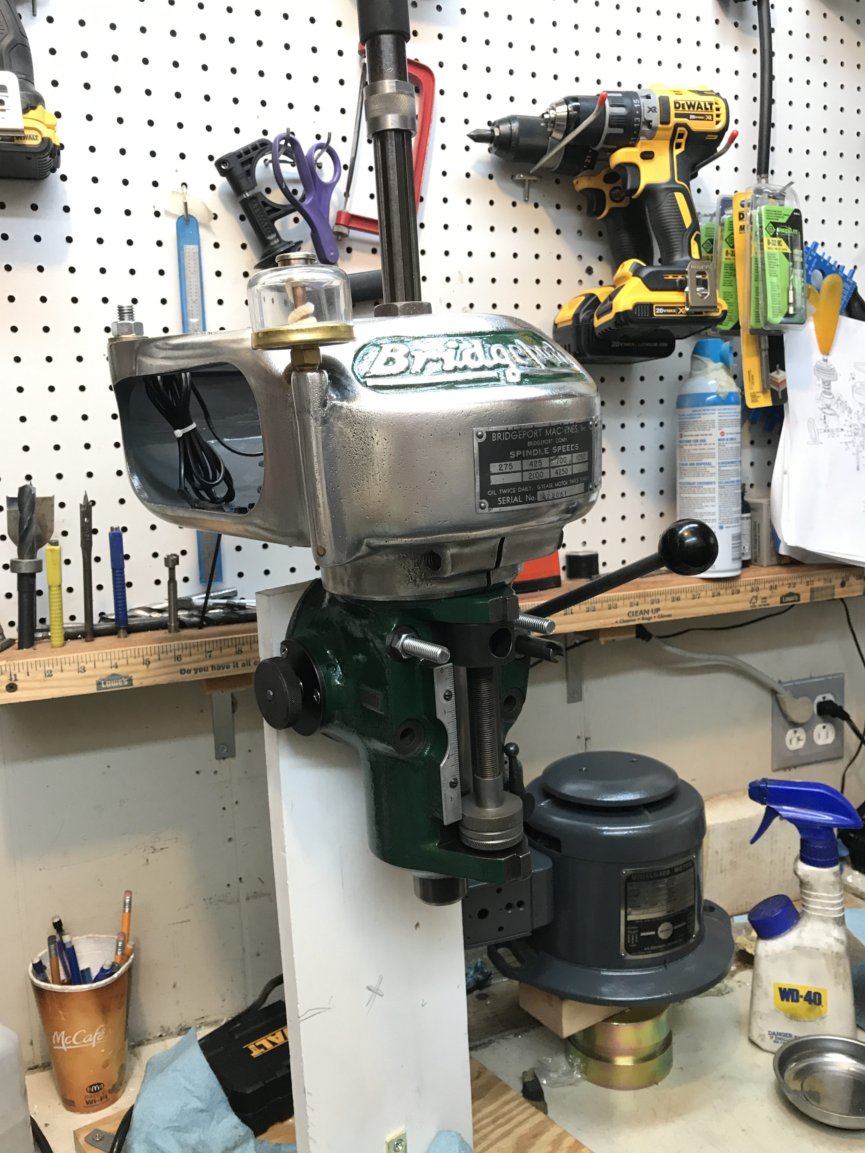
The next post will hopefully show some planning and machining of the parts needed to adapt this to the BM mill. I’d love to get it done soon and start making chips with this machine! I have another major project dividing my time however, which I may write about here a bit later. Until then…
Leave a Reply